Enerpac LU7-Series User Manual
Page 3
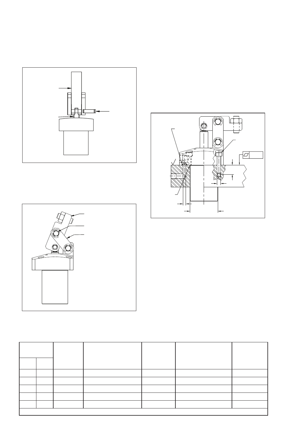
3.2 Arm Attachment
Place the clamp arm over the plunger end, lining up
the pivot pin holes. The clamp arm should extend
between the two links previously installed. Insert
the supplied short pivot pin through the arm and the
plunger, securing the parts together with the supplied
E-clips (See Figure 4).
Clamp Arm
Plunger
Figure 4
Then, insert the second long pivot pin through the
top holes on the links and through the top hole on
the clamp arm, securing it with the last two supplied
E-clips (See Figure 5).
Clamp Arm
Pivot Pin (long)
Link
Figure 5
3.3 Cylinder Mounting
The Enerpac 70 bar link clamp features a 4 bolt
flange style body for mounting the cylinder to the
fixture plate. Mounting bolts of the proper size and
length are supplied. Flange mounting requires the
machining of a through hole in the fixture plate or
mounting block and threads for the four (4) mounting
bolts. (See Figure 6 and Table 1).
Align the cylinder in the proper orientation to provide
clamping force to the part. Then, install the mounting
bolts and tighten per the value shown in Table 1.
Failure to properly tighten the mounting bolts can
result in damage to the cylinder and premature failure
of the clamp.
øD3
J
63
ø 4,8
Mounting Bolts
(included)
Manifold
O-Rings
(included)
Mtg. Hole
J2
0.004
.5mm x 45°
Figure 6
3.4 Oil Connections
The cylinder can be plumbed using either the
hydraulic ports on the side of the flange, or the
manifold O-ring ports on the underside of the flange.
When using the manifold O-ring ports, use a 4.8 mm
diameter feed passage. The feed passage should
align with the center of the O-ring.
Hydraulic Fittings
The Enerpac 70 bar link clamp is supplied with BSPP
ports in the side of the flange. Connect the oil supply
to these ports using fittings rated for a minimum of
70 bar [1000 psi] only. Single acting (spring return)
models are vented. The supplied vent fitting may be
removed if using the manifold port for the vented
port.
3
Table 1 - Specifications
Clamp
Force
1)
Mounting
Hole
Ø D3
mm
Mounting Bolt
Thread
J
Min. Depth
J2
mm
Manifold O-ring
2)
ARP No.
Lubricated
Bolt Torque
Nm
kN
lbs.
2
450
36.5
M5 x .08 x 30 mm long
12
568-010
8.0-9.0
3.5
787
42.5
M5 x .08 x 30 mm long
12
568-010
8.0-9.0
5
1124
48.5
M6 x 1.0 x 30 mm long
16
568-011
13.5-15.0
7
1574
54.5
M6 x 1.0 x 30 mm long
16
568-011
13.5-15.0
9
2023
60.5
M8 x 1.25 x 30 mm long
18
568-011
32.0-38.0
1)
At rated clamp point.
2)
O-rings and mounting bolts are included.
Pivot Pin
(short)