Enerpac LU7-Series User Manual
Page 2
2
®
Do not drop heavy objects on hose. A
sharp impact may cause internal damage
to hose wire strands. Applying pressure to
a damaged hose may cause it to rupture.
IMPORTANT: Do not lift hydraulic
equipment by the hoses or swivel
couplers. Use the carrying handle or other
means of safe transport.
CAUTION: Keep hydraulic equipment
away from flames and heat. Excessive
heat will soften packings and seals,
resulting in fluid leaks. Heat also weakens hose
materials and packings. For optimum performance
do not expose equipment to temperatures of 65 °C
[150 °F] or higher. Protect hoses and cylinders from
weld spatter.
DANGER: Do not handle pressurized
hoses. Escaping oil under pressure can
penetrate the skin, causing serious injury.
If oil is injected under the skin, see a doctor
immediately.
WARNING: Only use hydraulic cylinders in
a coupled system. Never use a cylinder
with unconnected couplers. If the cylinder
becomes extremely overloaded, components can fail
catastrophically causing severe personal injury.
IMPORTANT: Hydraulic equipment must
only be serviced by a qualified hydraulic
technician. For repair service, contact the
Authorized ENERPAC Service Center in your area. To
protect your warranty, use only ENERPAC oil.
WARNING: Immediately replace worn or
damaged parts with genuine ENERPAC
parts. Standard grade parts will break
causing personal injury and property damage.
ENERPAC parts are designed to fit properly and
withstand high loads.
3.0 INSTALLATION
The Enerpac 70 bar link clamp features an upper
flange design. The clamp can be mounted to the
fixture using the supplied mounting bolts. Oil can be
supplied to the clamp using either the BSPP hydraulic
ports on the flange or via the O-ring manifold ports
on the underside of the flange. The following sections
of this manual include detailed mounting instructions
that should be reviewed before attempting to install
the clamp on the fixture.
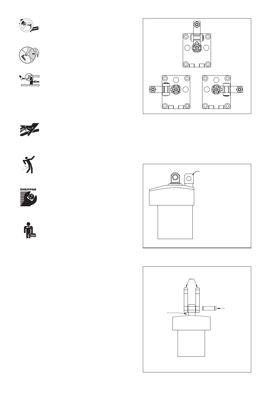
3.1 Clamp Arm Location
The Enerpac 70 bar link clamp contains an anchor
lug that is integral to the body. Models are available
that place this lug at a center, right or left position in
relation to the hydraulic ports (See Figure 1).
Center
Left
Right
Figure 1
To install the linkage components, line up the two (2)
links with the hole in the anchor lug. Insert one (1) of
the long pivot pins through the links and the anchor
lug. Secure the pivot pin in place using two (2) of the
supplied E-clips (See Figures 2 and 3).
Hole in anchor
post must line up
perpendicular to
direction of clamp
arm.
Figure 2
Pivot Pin
(long)
Links
Figure 3
Anchor
Post