Operation, Vent plug, Pressure and flow rate – Enerpac ST-121 User Manual
Page 9
OPERATION
Swing cylinders rotate 90° during the first portion of the stroke, continuing without
rotation for the final clamping stroke. The straight downward stroke is the clamping
stroke of the cylinder. Clamping force must be applied only during the vertical
travel, not during the swing motion.
A
CAUTION
— If clamping force is applied during the rotation portion of the stroke,
internal plunger damage will result.
— To ensure maximum cylinder performance and safety; be sure all
hydraulic connections, hoses, and fittings are properly sealed and fully
tightened.
— Be sure all items are rated to withstand system pressures. Under-rated
components will not withstand higher pressure. Using under-rated
components will lead to equipment damage and possible personal injury.
Vent Plug
Single-acting cylinders have a vented plug on the left side of the cylinder when you
are facing the hydraulic ports. To prevent entry of chips and coolant, the vent plug
must not be removed. If the vent plug is subjected to a continuous coolant flood
condition, attach tubing to the port using an SAE fitting, and run the tubing to a
non-contaminated area of the fixture.
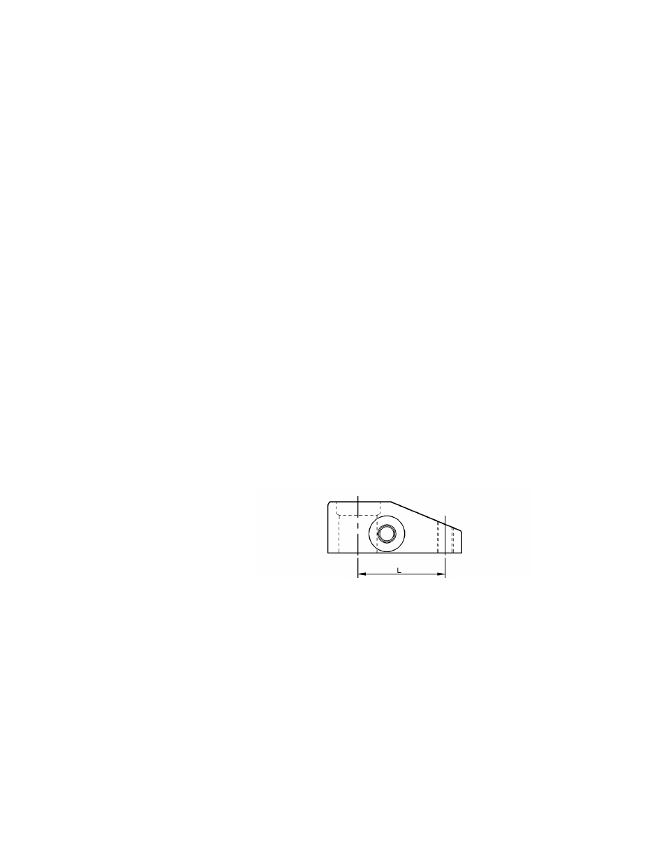
Pressure and Flow Rate
Clamp arm length (L) determines operating pressure setting and flow rate.
See Operating Specifications — Maximum Flow Rate Chart on page 2 for clamp
arm length, pressure setting and flow rate. Set operating pressure and flow rate
according to the limits established by the length of the clamp arm. Do not exceed
the load-to-length pressure ratios. As the arm length increases, the clamping force
and maximum operating pressure are reduced.
A
CAUTION
It is very important that you use the correct pressure and flow settings.
Operating outside these limits will cause damage to the swing cylinder.
Damage caused by exceeding rated pressure and maximum flow is NOT
COVERED BY WARRANTY.
9