Enerpac S-Series User Manual
Page 6
-
Use of extension pieces or long-reach
sockets is not recommended. They
increase torsional and bending stresses,
and reduce stability of the tool.
-
Always observe the maintenance
instructions.
6
ENGLISH
Fig. A
3
Assembly and adjustments
3.1
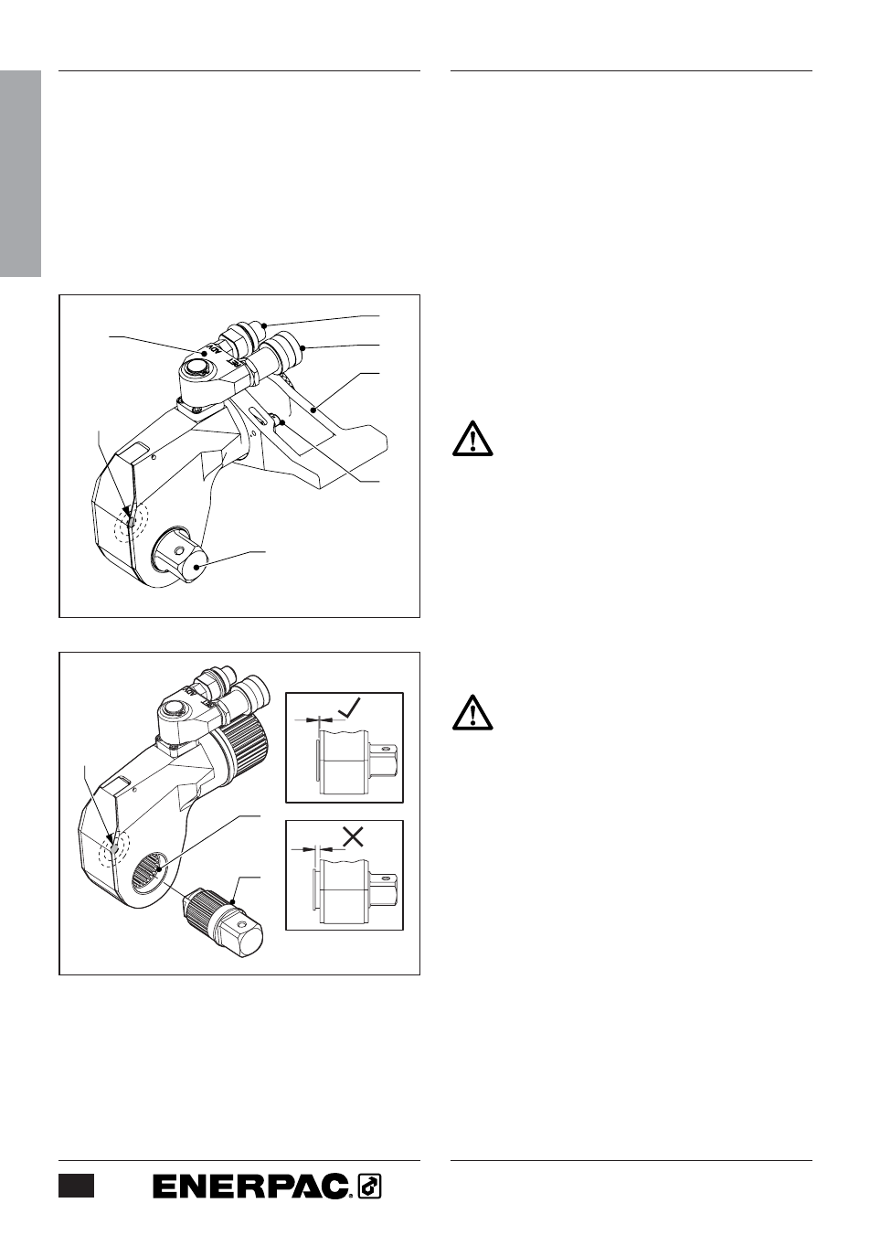
Overview and features (fig. A)
1
Drive shaft
2
Drive shaft release button
3
Swivel coupling
4
Advance hose connection
5
Return hose connection
6
Reaction arm
7
Reaction arm latch
3.2
To attach and remove the drive
shaft (fig. B)
Make sure to depressurize and
disconnect the tool from the hydraulic
supply first.
3.2.1 To attach the drive shaft
•
Insert the drive shaft (1) into the
ratchet (8).
•
Press the release button (2) and keep
it depressed.
•
Push and turn the drive shaft until it
locks into place.
Make sure the drive shaft fits tightly
into the ratchet.
3.2.2 To remove the drive shaft
•
Press the release button (2) and keep
it depressed.
•
Pull the drive shaft (1) until it is
released.
•
Remove the drive shaft from the
ratchet (8).
3.3
To select the drive direction (fig. B)
•
For tightening operations, fit the drive
shaft (1) to the tool as shown.
•
For loosening operations, fit the drive
shaft to the opposite side of the tool.
8
1
2
4
3
5
6
1
7
2
Fig. B