Main feedback – ElmoMC SimplIQ Digital Servo Drives-Guitar Installation Guide User Manual
Page 28
Guitar Installation Guide
Installation
MAN-GUIIG (Ver. 1.601)
28
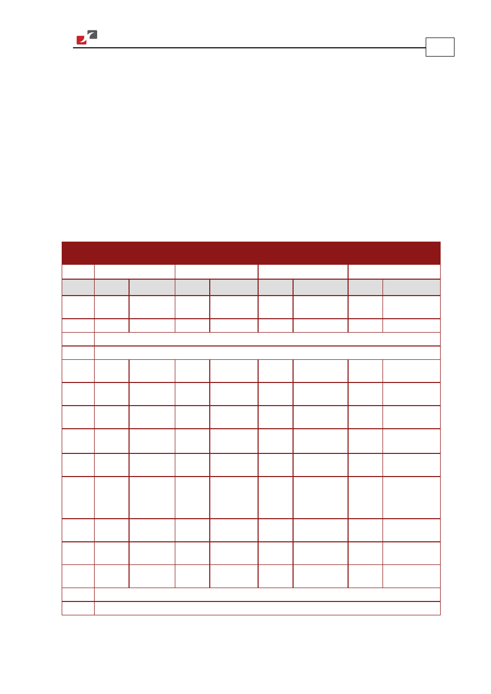
3.9. Main Feedback
The Main Feedback port is used to transfer feedback data from the motor to the drive.
The Guitar can accept any one the following devices as a main feedback mechanism:
•
Incremental encoder only
•
Incremental encoder with digital Hall sensors
•
Digital Hall sensors only
•
Incremental Analog (Sine/Cosine) encoder (option)
•
Resolver (option)
•
Tachometer (option)
•
Potentiometer (option)
•
Absolute Encoder (optional on the solo board)
Incremental
Encoder
Interpolated
Analog Encoder
Resolver
Tachometer and
Potentiometer
GUI-
XX
/
YYY
_
GUI -
XX
/
YYY
I
GUI -
XX
/
YYY
R
GUI-
XX
/
YYY
T
Pin (J2) Signal Function Signal Function Signal Function
Signal Function
1
+5V
Encoder/Hall
+5V supply
+5V
Encoder/Hall
+5V supply
+5V
Encoder/Hall
+5V supply
+5V
Encoder/Hall +5V
supply
2
SUPRET
Supply return SUPRET
Supply return SUPRET
Supply return
SUPRET
Supply return
3
ANALIN+ is used for Analog Input
4
ANALIN- is used for Analog Input
5
CHA
Channel A
A+
Sine A
S1
Sine A
Tac 1+
Tacho Input 1
Pos. (20 V max)
6
CHA-
Channel A
complement
A-
Sine A
complement
S3
Sine A
complement
Tac 1-
Tacho Input 1
Neg. (20 V max)
7
CHB
Channel B
B+
Cosine B
S2
Cosine B
Tac 2+
Tacho Input 2
Pos. (50 V max)
8
CHB-
Channel B
complement
B-
Cosine B
complement
S4
Cosine B
complement
Tac 2-
Tacho Input 2
Neg. (50 V max)
9
INDEX
Index
R+
Reference
R1
Vref f = 1/TS,
50 mA Max
POT
Potentiometer
Input (5 V Max)
10
INDEX-
Index
complement
R-
Reference
complement
R2
Vref
complement
f = 1/TS, 50 mA
Max
NC
-
11
HA
Hall sensor A
input
HA
-
NC
-
HA
Hall sensor A
input
12
HB
Hall sensor B
input
HB
-
NC
-
HB
Hall sensor B
input
13
HC
Hall sensor C
input
HC
-
NC
-
HC
Hall sensor C
input
14
LED_2_OUT (AOKLED cathode) is used for LED indication
15
LED_1_OUT (AOKLED anode) is used for LED indication
Table 3: Main Feedback Pin Assignments