Integrating the guitar on a pcb, Traces, Grounds and returns – ElmoMC SimplIQ Digital Servo Drives-Guitar Installation Guide User Manual
Page 21: Traces 3.5.2. grounds and returns
Guitar Installation Guide
Installation
MAN-GUIIG (Ver. 1.601)
21
3.5. Integrating the Guitar on a PCB
The Guitar is designed to be mounted on a PCB, either by soldering its pins directly to the PCB
or by using suitable socket connectors. In both cases the following rules apply:
3.5.1.
Traces
1.
The size of the traces on the PCB (thickness and width) is determined by the current
carrying capacity required by the application.
The rated continuous current limit (Ic)of the Guitar is the current used for sizing the
motor traces (M1, M2, M3 and PE) and power traces (VP+, PR and PE).
For control, feedbacks and Inputs/ outputs conductors the actual current is very small
but “generous” thickness and width of the conductors will contribute to a better
performance and lower interferences.
2.
The traces should be as short as possible to minimize EMI and to minimize the heat
generated by the conductors.
3.
The spacing between the high voltage conductors (VP+, PR, M1, M2, M3, VL) must be at
least:
Surface layer: 1.5 mm
Internal layer: 0.5 mm
Complying with the rules above will help satisfy UL safety standards, MIL-STD-275 and the
IPC-D-275 standard for non-coated conductors, operating at voltages lower than 200 VDC.
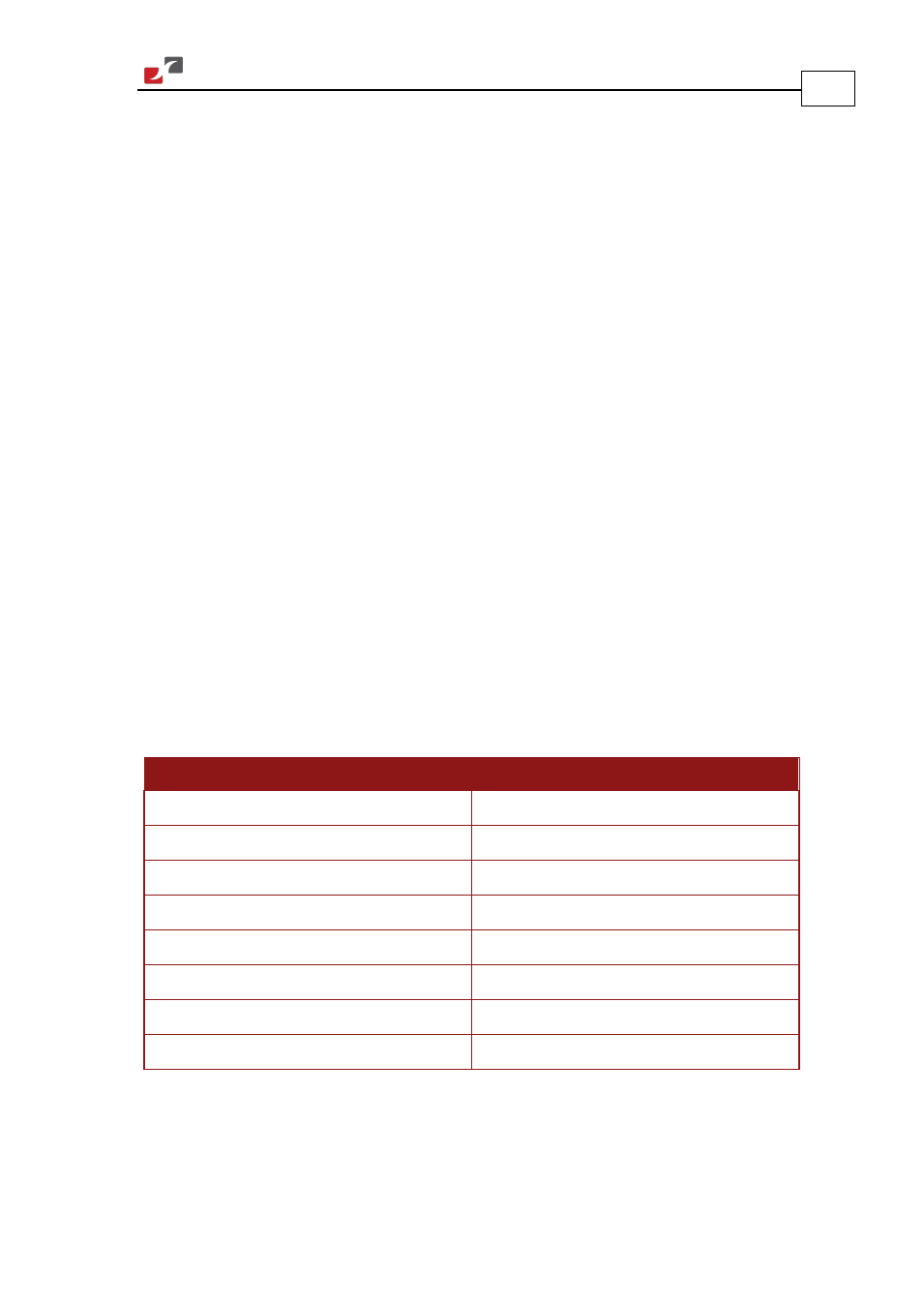
3.5.2.
Grounds and Returns
The “Returns” of the Guitar are structured internally in a star configuration. The returns in each
functional block are listed below:
Functional Block
Return Pin
Power
PR (Power Return)
Internal Switch Mode P. S.
PR (Power Return)
RS-232 Communications
RS232_COMRET (J1/3)
CAN Communications
CAN_COMRET (J1/30)
Control section
COMRET (J1/28)
Main Feedback
SUPRET (J2/2)
Aux. Feedback
SUPRET (J1/6)
Analog input
ANLRET (J2/2)