Resolver connection diagram, Port c – emulated encoder output (j2) – ElmoMC ExtrIQ Gold Line Servo Drives-Gold Panther User Manual
Page 43
Gold Panther Installation Guide
MAN-G-PANIG-EC (Ver. 1.000)
|Feedback
43
5.3.2.3.
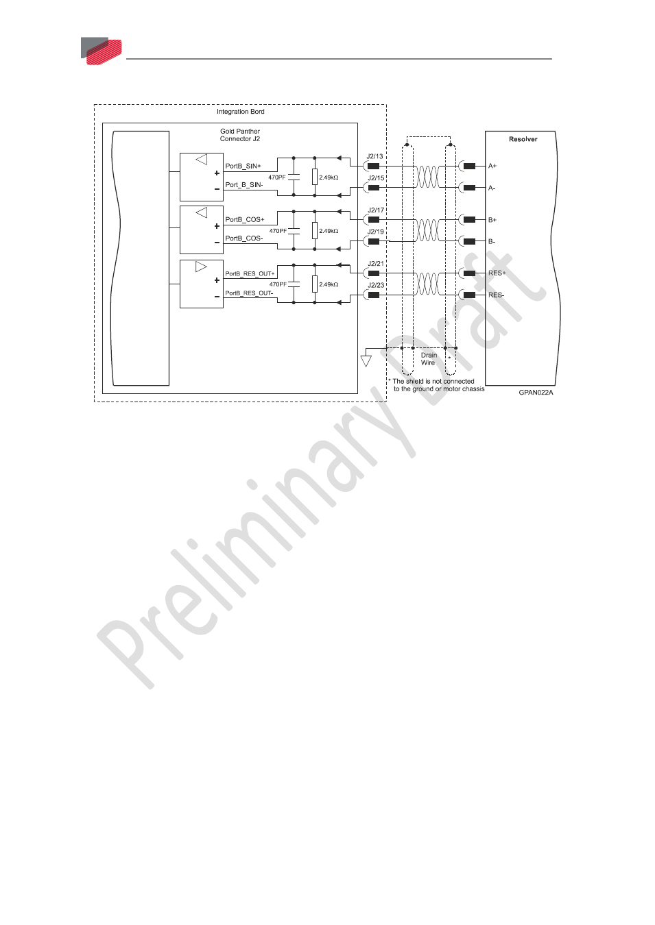
Resolver Connection Diagram
Figure 20: Port B – Resolver Connection Diagram
5.3.3.
Port C – Emulated Encoder Output (J2)
Port C provides emulated encoder output derived from port A or port B feedback inputs, or from
internal variables. The output options are:
•
Port A/B daisy chain (1:1) for incremental encoder
•
Encoder emulation: Emulate any input sensor, digital or analog, or use to emulate an internal
variable such as virtual profiler.
•
PWM output: any pair of outputs that is used as an encoder channel (e.g., channel A+ and
channel A-) can be configured by software to become PWM output.
•
Pulse & Direction output: The output pins that are assigned as channel A and channel B when
used as encoder out, can be configured by software to become pulse and direction outputs
respectively.
This port is used when:
•
The Gold Panther is used as a current amplifier to provide position data to the position
controller.
•
The Gold Panther is used in velocity mode, to provide position data to the position controller.
•
The Gold Panther is used as a master in follower or ECAM mode.