Det-Tronics C7050 A, C, G, P UV Flame Detector User Manual
Page 8
resistance is 16.14 ohm/1000 ft. or 53.0 ohm/km.) The
R7404 Controller will accommodate up to 16 detectors.
The detectors can be located up to 2000 feet (600
meters) from the controller. Shielded cable is required for
the “B” (signal) leadwires. As with any field device,
shielded cable on all wires provides maximum protection
from RFI/EMI sources.
SHIPPING WEIGHT (Approximate)—
Pounds
Kilograms
Controller
2.5
1.12
Detector (aluminum)
1.25
0.56
(stainless steel or brass)
2.25
1.0
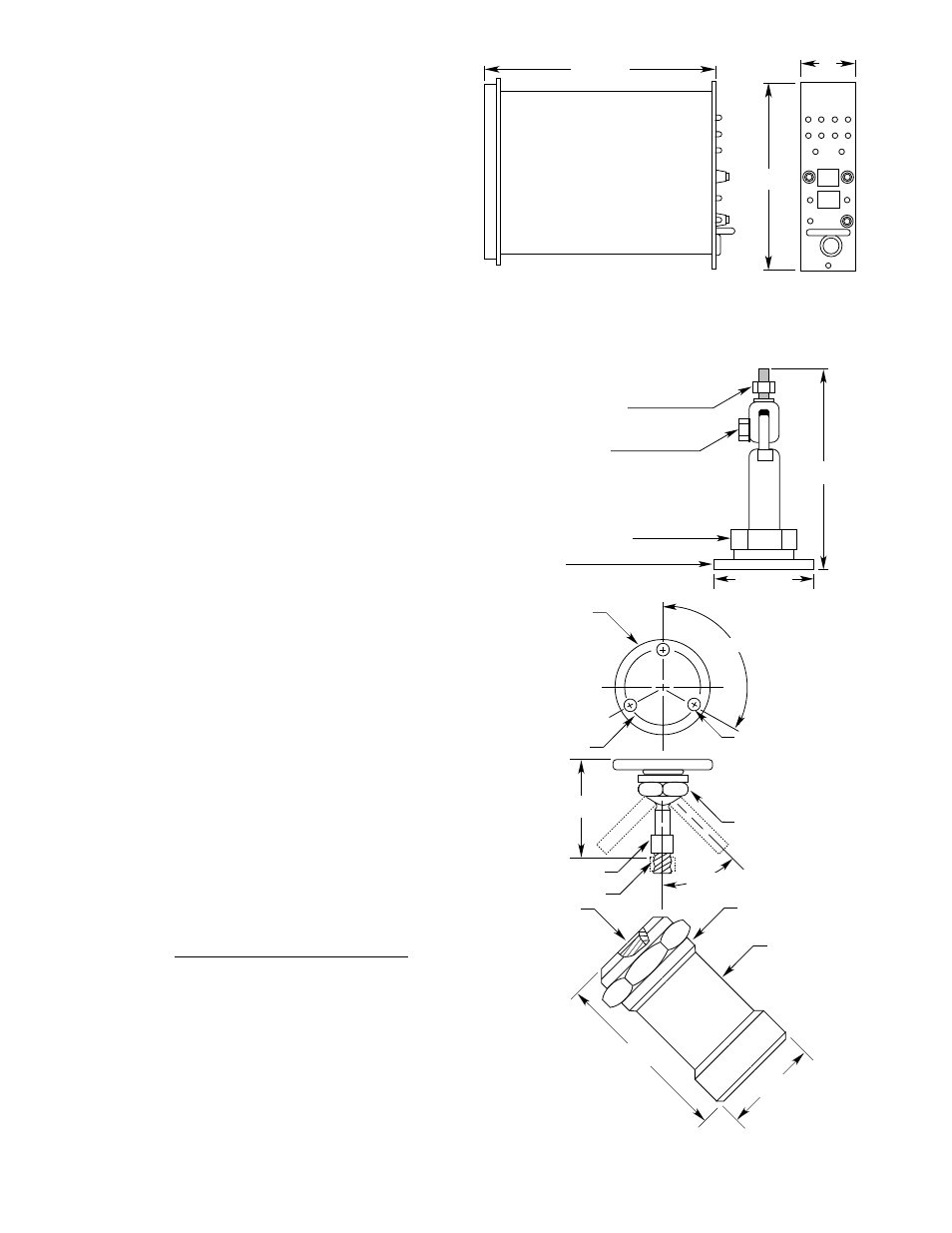
DIMENSIONS—
Refer to Figure 3 for dimensions of the controller and
Figure 4 for the detector and swivel mounting brackets.
Figure 5 shows the dimensions of the Q4004 Mounting
Cage. Cages that hold fewer devices are also available.
CONE OF VISION—
The C7050 Detector has a nominal 90 degree cone of
vision with the highest sensitivity along its central axis.
See Figure 7.
DETECTOR ENCLOSURE MATERIALS—
Models are available in anodized copper-free aluminum,
nickel-plated brass, or 316 stainless steel.
CERTIFICATIONS—
FMRC:
See Appendix A for details.
CSA:
Explosion-proof for Class I, Division 1,
Groups C and D.
Dust ignition-proof for Class II, Division 1,
Groups E, F, and G.
Enclosure Type 4 (Indoor and Outdoor
Use)
CSFM:
Explosion-proof for Class I, Division 1,
Groups B, C and D.
Dust ignition-proof for Class II, Division 1,
Groups E, F, and G.
CENELEC:
EEx d IIB+H2 T6 (T
amb
= –40°C to +77°C)
EEx d IIB+H2 T4 (T
amb
= –40°C to +125°C)
IP66
Special Conditions for Safe Use “X”:
The fused silica window is liable to be
damaged by impact. The detector should
be installed in such a manner as to pre-
vent the window from receiving mechani-
cal damage.
Russian
Performance Verified from –55°C to +75°C
Certification:
1Ex d IIB T6X (T
amb
= –40°C to +77°C)
1Ex d IIB T4/H2 X (T
amb
= –40°C to +125°C)
IP66
9.5 (242 MM)
7.0
(177 MM)
2.0
(50MM)
F234
Figure 3—Controller Dimensions in Inches (Millimeters)
6
5-1/4 INCHES
(133 MM)
2-1/2 INCHES
(64 MM)
MOUNTING BASE
1/2 INCH NUT USED TO ADJUST
ELBOW TO DESIRED ANGLE
1-3/8 INCH NUT USED TO ROTATE
SWIVEL/DETECTOR ASSEMBLY TO DESIRED POSITION
3/4 INCH NUT USED TO SECURE
DETECTOR TO SWIVEL MOUNT
B1323
Q9001H – USE FOR MOUNTING NICKEL/BRASS
AND STAINLESS STEEL C7050 DETECTORS
POSITIONING SWIVEL NUT
0.25 (6.4 MM) DIAMETER (3)
DETECTOR HOUSING
2-1/2 (64 MM) DIAMETER
TERMINAL CAP
2.00 (50.8 MM) DIAMETER
1/2 – 14 NPT
3/4 – 14 NPT
M20 x 1.5
M25 x 1.5 – 6H
Pg 16
5/16 – 18 UNC – 2A
DETECTOR LOCK NUT
CONDUIT OPTIONS:
OPTIONAL SWIVEL
MOUNTING BRACKET
(Q9001B, FOR ALUMINUM ONLY)
120
o
± 2
o
(2)
45
o
(2)
2-1/2
(64 MM)
2-1/2
(64 MM)
4-3/4
(121 MM)
G0121
Figure 4—Detector Dimensions in Inches (Millimeters)