Det-Tronics C7050 A, C, G, P UV Flame Detector User Manual
Page 15
tioning normally, but will not produce the desired
output in response to the input conditions. (Some
of the switches are not used and should be left in
the open position.)
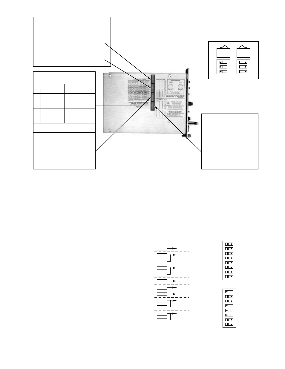
The rocker switches must be set
before
power is applied
to the system.
Do not plug the controller in or remove
it from the mounting rack while power is turned on.
1.
Zone and Detector Selection — Switch
Assemblies 1-1 to 1-8, and 2-1 to 2-8
Each zone can have either one or two detectors for
a maximum of 16 detectors in 8 zones connected to
one controller. Rockers 1-1 through 1-8 are used to
enable the detectors connected to position No. 1 of
each zone. Rockers 2-1 through 2-8 enable position
No. 2 of each zone. The appropriate rocker must be
set to the “Open” position for each detector con-
nected. Care must be taken when setting these
rockers. If a rocker is set open, but no detector is
connected in the location, the controller will show a
“2” fault on the lower digital display and the detector
display will show either a “1” or “2”, depending on
which detector is not connected in the zone. The
zone display will show the incorrectly set zone. If a
rocker is set closed, but a detector
is
connected,
the controller performs normally, but that detector is
eliminated from the Automatic
oi
test sequence, and
any faults that may occur in its circuit would not be
automatically identified. This condition can be found
only when performing the manual
oi
test procedure.
See Figure 14 for an example of selection switch
setting for a system using 12 detectors in 8 zones.
13
95-8242
SWITCH 3
FIRE LOGIC SETTING
OP = OPEN, CL = CLOSED, DC = DON'T CARE
A•B = A AND B
SENSITIVITY SELECTION
ROCKER 3-4 CLOSED = 64 CPS
ROCKER 3-3 CLOSED = 32 CPS
ROCKER 3-2 CLOSED = 16 CPS
ROCKER 3-1 CLOSED = 8 CPS
(ALL ROCKERS OPEN
OR ROCKER 3-1 CLOSED = 8 CPS)
THESE ROCKERS MAY BE USED
IN ANY COMBINATION FOR 8 CPS TO 120 CPS
3-8
CL
CL
CL
CL
OP
OP
OP
OP
3-7
DC
DC
DC
DC
3-6
DC
DC
OP
CL
ALL OPEN
1 CLOSED
2 CLOSED
3 CLOSED
3-5
OP
CL
DC
DC
A (1 OF ZONES 1 TO 4)
A (2 OF ZONES 1 TO 4)
B (1 OF ZONES 5 TO 8)
B (2 OF ZONES 5 TO 8)
A•B (1 OF 8 ZONES)
A•B (2 OF 8 ZONES)
A•B (3 OF 8 ZONES)
A•B (4 OF 8 ZONES)
FIRE LOGIC OUTPUTS
ROCKER POSITION
A0274
SWITCH ROCKER NUMBERS ARE DESIGNATED 1-1, 1-2, 1-3, ETC.
THE NUMBER PRECEDING THE DASH INDICATES THE SWITCH NUMBER.
THE NUMBER FOLLOWING THE DASH INDICATES THE ROCKER NUMBER
OF THE SWITCH INDICATED.
NOTE:
8
7
6
OPEN
8
7
6
OPEN
DOT INDICATES ROCKER DEPRESSED
ROCKER POSITIONS
CLOSED
OPEN
DETECTOR SELECTION SWITCHES 1 AND 2
THESE TWO SWITCHES PROGRAM THE MICROPROCESSOR
FOR EACH DETECTOR CONNECTED
SWITCH 1
PLACE ROCKER IN OPEN POSITION
FOR EACH DETECTOR IDENTIFIED AS NO. 1
IN ZONES 1 THROUGH 8
SWITCH 2
PLACE ROCKER IN OPEN POSITION
FOR EACH DETECTOR IDENTIFIED AS NO. 2
IN ZONES 1 THROUGH 8
}
}
SWITCH 4
TIME DELAY
AND LATCHING/NON-LATCHING OUTPUTS
ROCKER 8 – NOT USED
ROCKER 7 – NOT USED
ROCKER 6 – 8 SECOND DELAY
ROCKER 5 – 4 SECOND DELAY
ROCKER 4 – 2 SECOND DELAY
ROCKER 3 – 1 SECOND DELAY
ROCKER 2 – .5 SECOND DELAY
(ALL SWITCHES OPEN, TIME DELAY = 0)
ROCKER 1 – LATCHING OUTPUTS
WHEN ROCKER IS OPEN
Figure 13—Rocker Switches
8
7
6
5
4
3
2
1
8
7
6
5
4
3
2
1
OPEN
OPEN
C7050
ZONE 8
C7050
ZONE 7
C7050
C7050
ZONE 6
C7050
C7050
ZONE 5
C7050
ZONE 4
C7050
ZONE 3
C7050
ZONE 2
C7050
C7050
ZONE 1
C7050
DETECTOR ZONES
SELECTION SWITCHES
DETECTOR 1
ZONES 1 – 8
SWITCH 1
DETECTOR 2
ZONES 1, 2, 6, 7
SWITCH 2
TOTAL = 8 ZONES, 12 DETECTORS
A279
Figure 14—Detector and Zone Selection