Startup procedure, Checkout procedure, Manual oi check – Det-Tronics C7050 A, C, G, P UV Flame Detector User Manual
Page 20
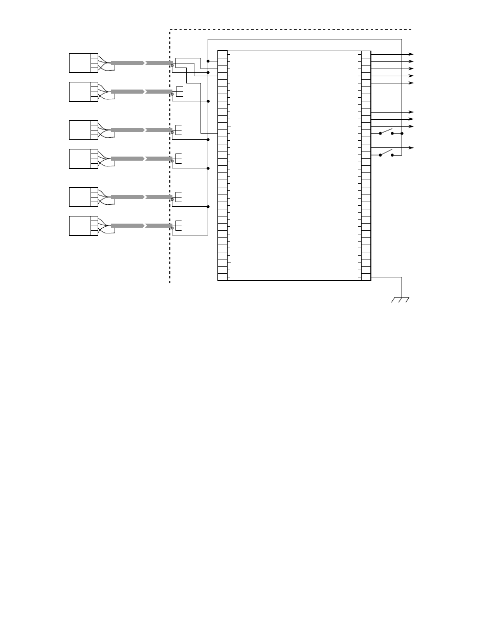
The Data Bus terminals (56 to 63) and the DMA (direct
memory access) and Data Strobe terminals (28 to 32)
provide external access to the microprocessor, which
permits inter-controller communication. For further infor-
mation, contact the Field Support Group at Detector
Electronics. (This feature is not available on all R7404
models.)
STARTUP PROCEDURE
CAUTION
Placing the controller in the Test mode inhibits its out-
puts, rendering the system incapable of actuating any
extinguishing or alarm circuits that are connected to it.
For maximum safety, however, secure output loads
(remove power from any devices that would normally
be actuated by the system) before manually testing
the system. Remember to place this same equip-
ment back into service when the test is complete.
1.
After setting the selection switches and making all
electrical connections, plug the controller into the
connector.
2.
Turn on power and perform Checkout Procedure.
3.
If the controller appears to be operating normally,
remove mechanical blocking devices and restore
power to the extinguishing loads.
NOTE
Be sure that the detector is correctly aimed at the
potential hazard and that no obstructions interfere
with its line of vision. In addition, UV absorbing
gases should not exist between the detector and
the potential hazard.
CHECKOUT PROCEDURE
CAUTION
When testing the system, be sure to secure all output
devices to prevent unwanted activation of this equip-
ment, and remember to place these same devices
back into service when the checkout is complete.
MANUAL
oi
CHECK
1.
Place the keylock switch in the TEST position.
— The FAULT and INHIBIT LEDs turn on
— Upper right display indicates the zone selected.
Upper left display identifies the detector of the
displayed zone.
18
1
2
3
4
5
6
7
8
9
10
11
12
13
14
15
16
17
18
19
20
21
22
23
24
25
26
27
28
29
30
31
32
+
–
(A) +290 VDC
B - INPUT 1
B - INPUT 2
B - INPUT 3
B - INPUT 4
B - INPUT 5
B - INPUT 6
B - INPUT 7
B - INPUT 8
D1-1
oi
DRIVER
D1-2
oi
DRIVER
D1-3
oi
DRIVER
D1-4
oi
DRIVER
D1-5
oi
DRIVER
D1-6
oi
DRIVER
D1-7
oi
DRIVER
D1-8
oi
DRIVER
D2-1
oi
DRIVER
D2-2
oi
DRIVER
D2-3
oi
DRIVER
D2-4
oi
DRIVER
D2-5
oi
DRIVER
D2-6
oi
DRIVER
D2-7
oi
DRIVER
D2-8
oi
DRIVER
DMA OUT AVAILABLE
DMA OUT
DMA IN
DATA STROBE
DMA IN AVAILABLE
33
34
35
36
37
38
39
40
41
42
43
44
45
46
47
48
49
50
51
52
53
54
55
56
57
58
59
60
61
62
63
64
ZONE OUTPUT 1
ZONE OUTPUT 2
ZONE OUTPUT 3
ZONE OUTPUT 4
ZONE OUTPUT 5
ZONE OUTPUT 6
ZONE OUTPUT 7
ZONE OUTPUT 8
FIRE LOGIC “A”
FIRE LOGIC “B”
ALARM OUTPUT
EXTERNAL RESET/INHIBIT
OUTPUTS INHIBITED
FAULT OUTPUT
EXTERNAL ACCEPT
STATUS & DET. OUTPUT S1
STATUS & DET. OUTPUT S2
STATUS & DET. OUTPUT S3
STATUS & DET. OUTPUT S4
STATUS & DET. OUTPUT S5
STATUS & DET. OUTPUT S6
STATUS & DET. OUTPUT S7
STATUS & DET. OUTPUT S8
DATA BUS 0
DATA BUS 1
DATA BUS 2
DATA BUS 3
DATA BUS 4
DATA BUS 5
DATA BUS 6
DATA BUS 7
CHASSIS (EARTH) GND
A
B
C
D
C7050
ZONE 1
A
B
C
D
C7050
ZONE 2
A
B
C
D
C7050
ZONE 3
A
B
C
D
C7050
A
B
C
D
C7050
FIRE ALARM CONTROL CABINET
A
B
D
A
B
D
J1-3
J1-5
J1-21
A
B
D
J1-3
J1-4
J1-20
A
B
D
JI13
J1-5
J1-13
A
B
D
J1-3
J1-6
J1-22
C0286
J2
R7404
J1
10 TO 38 VDC
}
A
B
C
D
C7050
A
B
D
J1-3
J1-6
J1-14
ALTERNATE METHOD OF TERMINATING SHIELDS,
FOR USE WHERE CODES PERMIT
Figure 23—Typical System - Six Detectors in Three Zones