Typical system applications – Det-Tronics C7050 A, C, G, P UV Flame Detector User Manual
Page 18
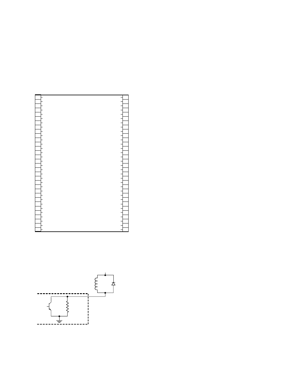
NOTE
External equipment that can generate transients
when switching (such as relays) must have a tran-
sient suppression device (diode) connected
across the coil at the time of installation. This will
safeguard the output transistors of the controller
against possible damage. Figure 21 illustrates an
inductive load with a diode used for transient sup-
pression.
TYPICAL SYSTEM APPLICATIONS
The following typical applications are examples only.
See Figures 22, 23 and 24. For assistance in adapting a
system to your individual requirements, contact the Field
Support Group at Detector Electronics.
The system illustrated in Figure 22 furnishes solid state
output signals from zones 1 to 5, Fire Logic A and B,
and the Alarm output. External Inhibit and External
Accept are shown connected for use in locations remote
from the controller. Other connections are not used in
this configuration.
External Inhibit/Reset (terminal 44) is a means of remote-
ly inhibiting the output circuits and resetting the con-
troller. External Accept (terminal 47) is a means of
remotely turning off the alarm output. These functions
can be performed by a computer interface, external
switches, or any interface that drives the input to less
than 0.5 vdc. Outputs Inhibited (terminal 45) is an out-
put that is driven low when the controller is in the
Outputs Inhibited mode (keylock switch in TEST or
RESET position or External Inhibit/Reset switch closed).
The system illustrated in Figure 23 furnishes solid state
output signals from zones 1 to 3, Fire Logic A and B,
and the Alarm output. External Inhibit and External
Accept are shown connected for use in locations remote
from the controller. Other connections are not used in
this configuration. In this illustration the detectors are
connected using a 3 wire shielded cable, with the shield
functioning as the C-lead.
NOTE
Wiring codes in many areas do not permit the
detectors to be wired using the method shown in
Figure 23. Therefore, this should be considered an
alternate method for use only where codes allow.
The system illustrated in Figure 24 furnishes solid state
output signals from zones 1 through 8, Fire Logic A and
B, and the Alarm output. External Accept and External
Inhibit are shown connected for use in locations remote
from the controller. Other connections are not used in
this configuration.
Status and detector output terminals 48 to 55 provide
binary output representations of the front panel digital
displays for zone, detector, and system status. Tables 3
and 4 list the identification codes and the logic states of
the “Fault” and “Outputs Inhibited” bits for the various
status conditions.
Under “normal” (no fault) conditions, the Fault output is
energized (logic 1).
16
100K
R7484
OPEN COLLECTOR OUTPUT
1N4004
TYPICAL
+60 VDC MAXIMUM
C1289
Figure 21—Transient Suppression Device
1
2
3
4
5
6
7
8
9
10
11
12
13
14
15
16
17
18
19
20
21
22
23
24
25
26
27
28
29
30
31
32
+
–
(A) +290 VDC
B - INPUT 1
B - INPUT 2
B - INPUT 3
B - INPUT 4
B - INPUT 5
B - INPUT 6
B - INPUT 7
B - INPUT 8
D1-1
oi
DRIVER
D1-2
oi
DRIVER
D1-3
oi
DRIVER
D1-4
oi
DRIVER
D1-5
oi
DRIVER
D1-6
oi
DRIVER
D1-7
oi
DRIVER
D1-8
oi
DRIVER
D2-1
oi
DRIVER
D2-2
oi
DRIVER
D2-3
oi
DRIVER
D2-4
oi
DRIVER
D2-5
oi
DRIVER
D2-6
oi
DRIVER
D2-7
oi
DRIVER
D2-8
oi
DRIVER
DMA OUT AVAILABLE
DMA OUT
DMA IN
DATA STROBE
DMA IN AVAILABLE
ZONE OUTPUT 1
ZONE OUTPUT 2
ZONE OUTPUT 3
ZONE OUTPUT 4
ZONE OUTPUT 5
ZONE OUTPUT 6
ZONE OUTPUT 7
ZONE OUTPUT 8
FIRE LOGIC “A”
FIRE LOGIC “B”
ALARM OUTPUT
EXTERNAL RESET/INHIBIT
OUTPUTS INHIBITED
FAULT OUTPUT
EXTERNAL ACCEPT
STATUS & DET. OUTPUT S1
STATUS & DET. OUTPUT S2
STATUS & DET. OUTPUT S3
STATUS & DET. OUTPUT S4
STATUS & DET. OUTPUT S5
STATUS & DET. OUTPUT S6
STATUS & DET. OUTPUT S7
STATUS & DET. OUTPUT S8
DATA BUS 0
DATA BUS 1
DATA BUS 2
DATA BUS 3
DATA BUS 4
DATA BUS 5
DATA BUS 6
DATA BUS 7
CHASSIS (EARTH) GND
33
34
35
36
37
38
39
40
41
42
43
44
45
46
47
48
49
50
51
52
53
54
55
56
57
58
59
60
61
62
63
64
J2
R7404
J1
10 TO 38 VDC
}
SOLID STATE OUTPUTS MUST BE TRANSIENT PROTECTED, SEE TEXT FOR DETAILS
*
D0284
*
Figure 20—R7404 Terminal Configuration (Standard Model)