Det-Tronics C7050 A, C, G, P UV Flame Detector User Manual
Page 16
2.
Controller Sensitivity — Rockers 3-1 to 3-4
Rockers 3-1 to 3-4 are used to program controller
sensitivity in 8 cps increments.
3-1 closed —
8 cps
3-2 closed — 16 cps
3-3 closed — 32 cps
3-4 closed — 64 cps
The values of the closed rockers are added togeth-
er. The rockers can be set in any combination to
give the sensitivity setting selected for the applica-
tion, up to 120 cps.
NOTE
If no rockers are closed, or if only rocker 3-1 is
closed, the controller responds to an 8 cps signal
from the detector.
Refer to Figure 15 for an example of a 24 cps setting.
3.
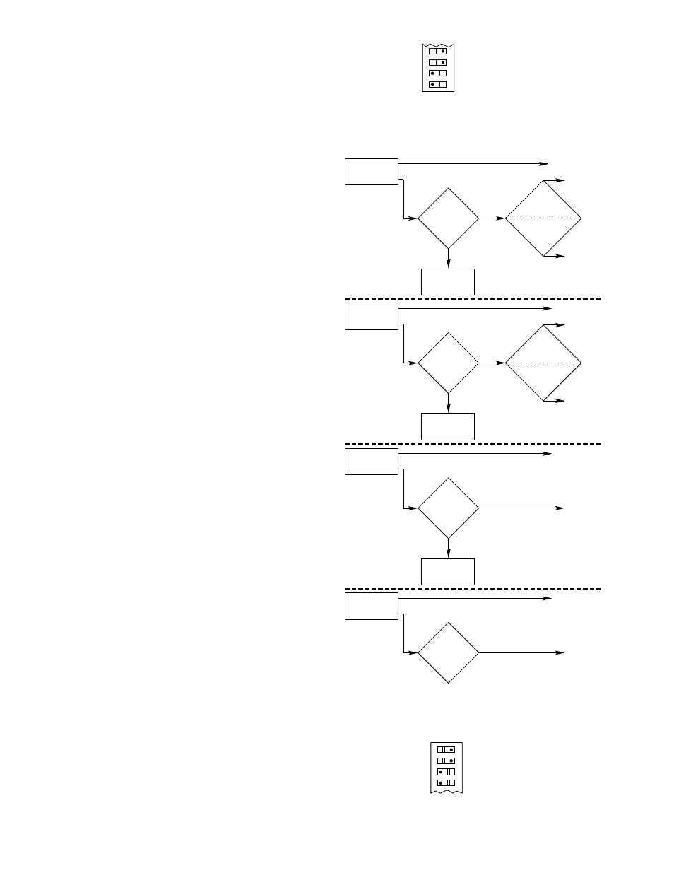
Fire Logic (Voting) — Rockers 3-5 to 3-8
Rockers 3-5 to 3-8 select the voting requirements,
which can be Fire Logic A and B common (8 zones
voting) or Fire Logic A (4 zones voting) separate
from Fire Logic B (4 zones voting). When separate,
Fire Logic A consists of zones 1 to 4, and Fire Logic
B consists of zones 5 to 8. See Figure 16.
NOTE
When the outputs are set for non-latching opera-
tion, the voting process will actuate the Fire Logic
output(s) only if the pre-selected number of voting
zones “see” fire at the same time. When the out-
puts are set for latching operation, the voting pro-
cess will actuate the Fire Logic output(s) when vot-
ing criteria have been met, even if fire is not being
seen by each voting zone at the same time.
Separate - Rocker 3-8 closed
Rocker 3-5 programs Fire Logic A (zones 1 to 4)
— when open, votes one of four zones
— when closed, votes two of four zones.
Rocker 3-6 programs Fire Logic B (zones 5 to 8)
— when open, votes one of four zones
— when closed, votes two of four zones
Fire Logic A and B Common — Rocker 3-8 open
3-5, 3-6, 3-7 open — votes one of eight zones
3-5 closed; 3-6 and 3-7 open — votes two of
eight zones
3-5 and 3-6 closed; 3-7 open — votes three of
eight zones
3-5, 3-6, 3-7 closed — votes four of eight zones
In the example illustrated in Figure 17, the setting is
for 3 of 8 zones voting.
14
8
7
6
5
3 OF 8 ZONES VOTING
SWITCH 3
A0280
OPEN
Figure 17—Fire Logic Setting
NO
NO FIRE LOGIC
OUTPUT
ANY ONE OR
MORE ZONES
SEE FIRE
ONE ZONE
SELECTED?
B0288
ONE OF
FOUR
ZONES SELECTED
YES
ONE OF EIGHT
ZONES
SELECTED
FIRE
LOGIC
SELECTED
ZONE OUTPUT(S)
FIRE LOGIC
OUTPUT
A OR B
FIRE LOGIC
OUTPUT
A AND B
NO
NO FIRE LOGIC
OUTPUTS
ANY TWO OR
MORE ZONES
SEE FIRE
TWO ZONES
SELECTED?
TWO OF
FOUR
ZONES SELECTED
YES
TWO OF EIGHT
ZONES
SELECTED
ZONE OUTPUTS
FIRE LOGIC
OUTPUT
A OR B
FIRE LOGIC
OUTPUT
A AND B
NO
NO FIRE LOGIC
OUTPUTS
ANY THREE OR
MORE ZONES
SEE FIRE
THREE ZONES
SELECTED?
YES
ZONE OUTPUTS
FIRE LOGIC
OUTPUT
A AND B
ANY FOUR OR
MORE ZONES
SEE FIRE
FOUR ZONES
SELECTED?
YES
ZONE OUTPUTS
FIRE LOGIC
OUTPUT
A AND B
Figure 16—Fire Logic Flow Chart
4
3
2
1
OPEN
3-1 CLOSED = 8 CPS
3-2 CLOSED = 16 CPS
TOTAL SENSITIVITY = 24 CPS
SWITCH 3
A0281
Figure 15—Controller Sensitivity Setting