Mounting and wiring procedure – Det-Tronics X3300EXE Protect-IR Multispectrum IR Flame Detector User Manual
Page 7
MOUNTING AND WIRING PROCEDURE
Refer to the procedure below and the listed figures to
mount and wire the X3300.
Figure 1 – Detector Orientation Relative to Horizon
Figure 2 – Wiring Terminal Identification
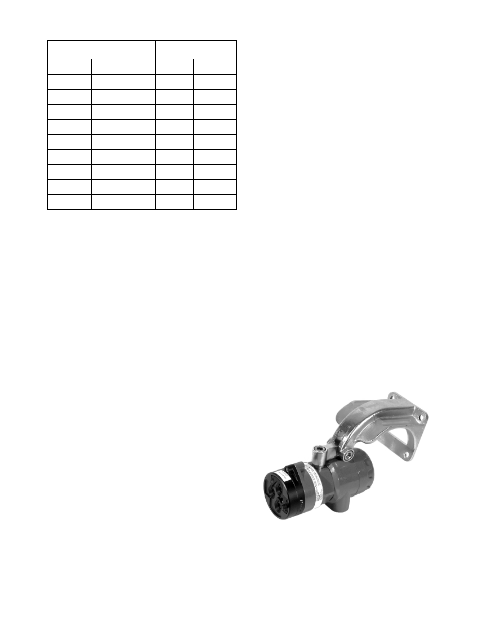
Figure 3 – X3300 with Q9033 Swivel Mount
Figure 4 – Front View of the X3300
Figure 5 – X3300 Terminal Block
Figure 6 – A Typical System
Figure 7 – X3300 Detector with 4 to 20 mA Output
oi
PLATE ORIENTATION
Refer to Figure 4 and insure that the
oi plate will be
oriented as shown when the X3300 is mounted and
sighted. This will ensure proper operation of the
oi
system and will also minimize the accumulation of
moisture and contaminants between the
oi plate and
the viewing windows. The
oi plate includes an arrow,
which should be pointed in the up direction, indicating
that the
oi plate and detector are correctly oriented.
IMPORTANT
The
oi
plate must be securely tightened to ensure
proper operation of the
oi
system.
INSTALLATION USING Q9033 MOUNTING
BRACKET
1.
Install the swivel mounting bracket assembly on the
wall. The installation surface should be free of
vibration. Refer to Figure 8 for dimensions of the
Q9033 swivel mount.
2.
Make field connections following local ordinances
and guidelines in this manual. Refer to Figures 2
and 6. If the detector is equipped with 4 to 20 mA
output, refer to Figure 7.
NOTE
Connect the shield to power supply minus (circuit
ground) at the detector end. At the fire panel end,
connect the shield and power supply minus to
chassis ground through a 0.47 µF 400 Volt non-
polarized capacitor (not supplied).
3.
Check all field wiring to be sure that the proper
connections have been made.
IMPORTANT
Do not test any wiring connected to the detector
with a meg-ohmmeter. Disconnect wiring at the
detector before checking system wiring for
continuity.
4.
Make the final sighting adjustments and ensure that
the mounting bracket hardware is tight.
5
95-8502
COLOR
FUNCTION
RELAY
4 TO 20 MA
WHITE
BLACK
RED
COLOR
WHITE
BLACK
RED
GRAY
PURPLE
BROWN
BLUE
GREEN
GREEN
MANUAL Oi
DC –
DC+
FUNCTION
MANUAL Oi
DC –
DC+
FAULT NO
FAULT C
FIRE NO
FIRE C
CHASSIS
CHASSIS
WHT/BRN
WHT/RED
4 TO 20 (–)
4 TO 20 (+)
A1977
1
2
3
4
5
6
7
8
TERMI-
NAL #
Figure 2—Wiring Terminal Identification
Figure 3—X3300 with Q9033 Mounting Bracket