Optical integrity ( oi), Startup procedure – Det-Tronics X3300EXE Protect-IR Multispectrum IR Flame Detector User Manual
Page 10
OPTICAL INTEGRITY (
oi)
AUTOMATIC
oi
The X3300 includes the Automatic Optical Integrity (
oi)
feature — a calibrated performance test that is
automatically performed once per minute to verify
complete detector operation capabilities. No testing
with an external test lamp is required. The detector
automatically performs the same test that a
maintenance person with a test lamp would perform —
once every minute, 60 times per hour. A successful
automatic
oi test
does not
produce an alarm condition.
The Protect•ir signals a fault condition when less than
50% of the detection range remains. This is indicated
by the Fault relay and is evident by the amber color of
the LED on the face of the detector. See the
“Troubleshooting” section for further information.
MANUAL
oi
The detector also incorporates a manual
oi feature that
provides the same test as the automatic
oi, and in
addition actuates the Alarm relay to verify output
operation. The manual
oi feature is available in all
models and can be performed at any time.
This test
requires bypass of all extinguishing devices to avoid
release resulting from a successful test.
The manual
oi test is activated by connecting the white
lead to power supply minus. This places the detector in
a special operating mode. First, the device de-latches
any latching outputs. Next, the IR emitters are activated.
If the resulting signals meet the test criteria, the Alarm
relay changes state and the indicating LED changes to
red. This condition remains until the white lead is
disconnected from dc minus. If the test criteria are not
met, no alarm is produced and no fault is generated.
See the “Troubleshooting” section for further details.
STARTUP PROCEDURE
When installation of the equipment is complete, perform
the “Fire Alarm Test” below.
Allow 20 to 30 minutes for the detector optics to reach
equilibrium. Housing will be warm to the touch.
8
24 VDC
4 TO 20 MA
PLC
–
+
875
Ω
MAX
AT 24 VDC
–
–
4 TO 20
MA
Oi
–24 VDC
+24 VDC
1
2
3
4
5
+
+
A2005
Oi TEST1
2
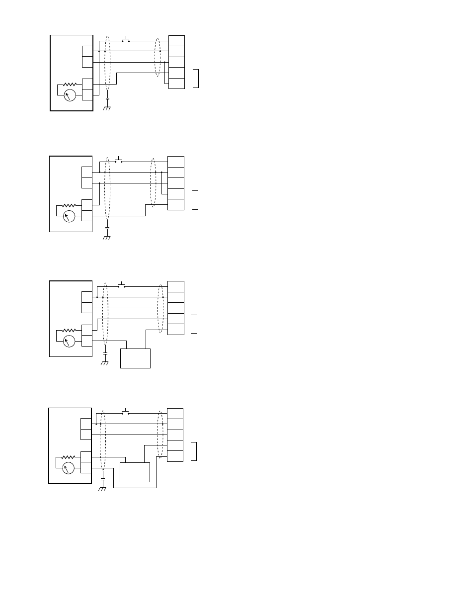
Figure 7A—X3300 Detector Wired for Non-Isolated 4 to 20 ma
Current Output (Sourcing)
24 VDC
4 TO 20 MA
PLC
–
+
875
Ω
MAX
AT 24 VDC
–
–
4 TO 20
MA
Oi
–24 VDC
+24 VDC
1
2
3
4
5
+
+
A2006
Oi TEST1
2
Figure 7B—X3300 Detector Wired for Non-Isolated 4 to 20 ma
Current Output (Sinking)
24 VDC
4 TO 20 MA
PLC
–
+
24 VDC
–
+
875
Ω
MAX
AT 24 VDC
–
–
4 TO 20
MA
Oi
–24 VDC
+24 VDC
1
2
3
4
5
+
+
A2007
Oi TEST1
2
Figure 7C—X3300 Detector Wired for Isolated 4 to 20 ma
Current Output (Sourcing)
24 VDC
4 TO 20 MA
PLC
–
+
24 VDC
–
+
875
Ω
MAX
AT 24 VDC
–
–
4 TO 20
MA
Oi
–24 VDC
+24 VDC
1
2
3
4
5
+
+
2008A
Oi TEST1
2
Figure 7D—X3300 Detector Wired for Isolated 4 to 20 ma
Current Output (Sinking)
NOTES:
1.INDIVIDUAL MANUAL oi TEST SWITCHES CAN BE
INSTALLED REMOTELY OR A DETECTOR SELECTOR AND
ACTIVATION SWITCH CAN BE INSTALLED AT THE FIRE
PANEL. TEST SWITCHES ARE NOT SUPPLIED.
2.SHIELD IS CONNECTED TO EARTH GROUND THROUGH
A 0.47µF/400V FILM CAPACITOR.