Installation, Configuration – Det-Tronics EQ3750ASH EQP Addressable Smoke & Heat (ASH) Module User Manual
Page 6
4.2
95-8654
6
CERTIFICATION —
FM / CSA:
Class
I
, Div. 2, Groups A, B, C, D (T4).
Class
I
, Zone 2, Group
II
C (T4).
ATEX:
II
3 G
Ex nA nC
II
C T4 Gc
DEMKO 10 ATEX 150744X
Tamb = –40°C to +85°C.
Compliance with: EN 60079-0:2012
EN 60079-15:2010.
Special conditions for safe use:
The EQ3750ASH shall be used in an area of no more
than pollution degree 2 per IEC 60664-1, and in an
enclosure with a tool removal cover that complies with
all relevant requirements of EN 60079-15, rated at least
IP54, and be connected to supply circuits where the
rated voltage cannot be exceeded by 40% caused by
transient disturbances.
The EQ3750ASH may only be installed, connected or
removed when the area is known to be non-hazardous.
The maximum surface temperature inside the EQ3750ASH
does not exceed 130°C.
Installation instructions:
For ambient temperatures below –10°C and above
+60°C, use field wiring suitable for both minimum and
maximum ambient temperatures.
The screw terminals are to be tightened with a minimum
torque of 0.5 Nm.
IECEx:
ULD 10.0004X
Ex nA nC
II
C T4 Gc
Tamb = –40°C to +85°C.
Compliance with: IEC 60079-0:2011
IEC 60079-15:2010
The ASH Module can not be used for
applications that fall within the scope
of the CPD directive.
US Coast Guard: As part of the EQP System. Reference
the EQP instruction manual (95-8533)
for more details.
installation
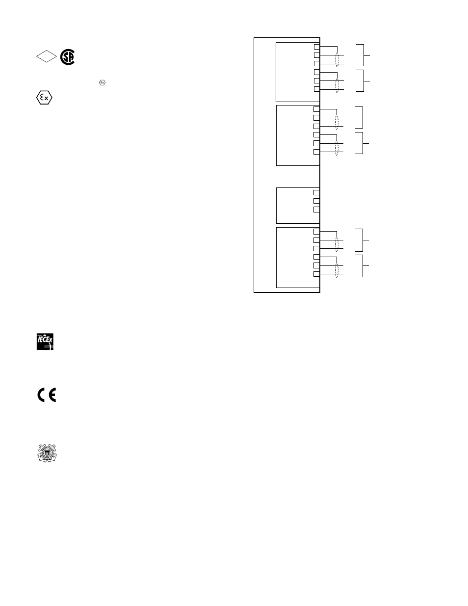
All electrical connections are made to the field wiring
connectors furnished with the module. Refer to Figure 7
for identification of module wiring terminals.
conFiguration
SETTING ASH MODULE NETWORk ADDRESS
One unique network address must be assigned to the
ASH Module. The address is set by the 8 switch DIP
assembly on the module (see Figure 8). The address
is binary coded and is equal to the added value of all
closed switches.
Det-Tronics’ S
3
Safety System Software is used for device
configuration. For complete configuration details, please
refer to the S
3
User’s Guide (95-8560).
LON
S-LOOP
7
8
9
10
11
12
COM 1 SHLD
COM 1 B
COM 1 A
COM 2 SHLD
COM 2 B
COM 2 A
SHLD
B
A
SHLD
B
A
LON FROM
PREVIOUS DEVICE
LON TO
NEXT DEVICE
LOOP IN
LOOP OUT
P2
P3
P1
SHLD
L1 – IN
L2 + IN
L1 – OUT
L2 + OUT
SHLD
SHLD
L1 –
L2 +
SHLD
L1 –
L2 +
DBG**
13
14
15
16
17
18
19
20
21
COM
RX
TX
POWER
1
2
3
4
5
6
SHLD
–
+
SHLD
–
+
SHLD
*
–
+
SHLD
*
–
+
24 VDC
INPUT VOLTAGE
24 VDC
INPUT VOLTAGE
EQ3750ASH
*
SHIELDS ON POWER WIRES ARE OPTIONAL
UNLESS REQUIRED BY LOCAL CODES.
**
FOR FIELD SERVICE USE ONLY.
B2534
Figure 7—ASH Module wiring Terminals
FM
APPROVED
®