Det-Tronics EQ3750ASH EQP Addressable Smoke & Heat (ASH) Module User Manual
Page 4
4.2
95-8654
4
pOWER-Up SEQUENCE
Set the ASH Module network address prior to applying
power. Make sure all the necessary connections are made
between the ASH Module and the Controller. At power-up
the “PWR” (Power) LED will illuminate and remain steady.
FAULTS
When a fault condition occurs, a yellow LED on the front
panel of the ASH Module will become active. There are 4
yellow LEDs for different categories of faults.
Module faults
A module fault occurs when a fault is detected within the
ASH Module, such as:
• Low voltage fault
• Memory fault
• Crystal oscillator fault
• Battery fault.
Loop faults
A loop fault is related to the Apollo device’s loop
communication and configuration, such as:
• Open loop
• Shorted loop
• Device missing
• Extra device
• Wrong device
• Multiple devices.
Loop device faults
A loop device fault is related to an individual device on the
loop, and is typically fixed by replacing the faulty device.
Any of the following faults can be categorized as a loop
device fault:
• Integrity check fault
• Device open
• Device short
• Device hardware faults
• Drift warning
• Earth fault.
Ground faults
Ground faults occur when a short or partial short exists
between the loop wiring and earth on the Apollo loop. There
is a local dedicated LED indicator that activates when there
is either a positive or negative ground fault.
CONTROL MESSAGE
The control message manages loop device specific
commands, such as integrity check, LED, relay and sound
control. The control message is transmitted from the
controller every 20 seconds, or immediately when there is
a change in the state of an output channel. A fault will be
annunciated if the control message is not received at the
controller within 2 minutes.
INTEGRITy CHECk
Integrity checks are internal tests that are performed on loop
devices that support the integrity check feature. All Apollo
Discovery detectors and manual call points are equipped with
the integrity check feature. The integrity check may be initiated
and monitored via the ASH Module point display in S
3
.
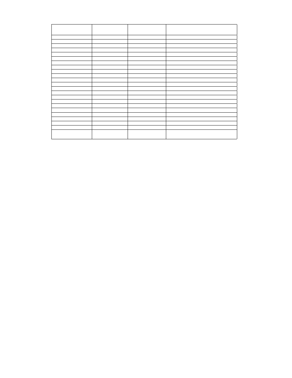
Table 3—List of Supported Devices
ApOLLO
SpEC SHEET
DET-TRONICS
pART NUMbER
ApOLLO
pART NUMbER
DEvICE NAME
PP2052
000515-501
58000-500
Apollo Ionization Smoke, EU
PP2052
000515-502
58000-600
Apollo Optical Smoke Detector, EU
PP2052
000515-503
58000-400
Apollo Heat Detector, EU
PP2052
000515-504
58000-700
Apollo Multisensor, EU
PP2052
000515-505
58000-300
Apollo Carbon Monoxide Detector, EU
PP2092
000515-509
55000-847
Apollo Input / Output Unit, with Isolator
PP2094
000515-510
55000-852
Apollo Sounder Control Unit
PP2084
000515-511
55000-841
Apollo Switch Monitor Plus
PP2052
000515-512
58100-908
Apollo Manual Call, with Isolator
PP2052
000515-513
58100-951
Apollo Manual Call, with Isolator, IP66
PP2267
000515-515
55000-278
Apollo Sounder, 100dB, Red
PP2267
000515-516
55000-274
Apollo Sounder, 100dB, Red, IP66
PP2156
000515-517
55000-877
Apollo Beacon, Red
PP2267
000515-518
55000-293
Apollo Sounder / Beacon, with Isolator
PP2390
000515-551
58000-550
Apollo Ionization Smoke, NA
PP2390
000515-552
58000-650
Apollo Optical Smoke Detector, NA
PP2390
000515-553
58000-450
Apollo Heat Detector, NA
PP2390
000515-554
58000-750
Apollo Multisensor, NA
39117-468
000515-557
55000-750
Apollo Isolator, NA
PP2390
000515-559
55000-806
Apollo Priority Switch Monitor, NA
PP2390
000515-560
55000-825
Apollo Sounder Control Module, NA
PP2390
000515-561
55000-820
Apollo Input / Output Module, NA
39214-387
000515-562
55000-765*
Apollo Mini Monitor Module, NA or Apollo
Priority Mini Switch Monitor, NA
* The device type depends on the priority switch setting on the device.
NA = North American Approvals
EU = European Approvals