Theory of operation – Det-Tronics EQ3750ASH EQP Addressable Smoke & Heat (ASH) Module User Manual
Page 2
4.2
95-8654
2
theory oF operation
During normal operation, the ASH Module continuously
checks the loop for alarm and fault conditions and
executes user defined programmed logic that coordinates
the control of the field devices. The ASH Module reports
any device based fault and alarm conditions to the EQP
Controller.
The ASH Module can support different Apollo Discovery
and XP95 devices (see Table 3). The supported devices
include smoke detectors, heat detectors, manual calls,
sounders, beacons and I/O modules. The addressable
devices are configured individually via the ASH Apollo
Editor in the S
3
software.
To ensure reliable system operation, the ASH Module can
continuously monitor its input and output circuits for open
and short circuit conditions. The EQP Controller also
continuously monitors the status of the ASH Module as
well as the status of each device connected to the ASH
Module.
The controller communicates with the ASH Module by
continuously broadcasting a heartbeat signal over the
LON (Figure 1). This heartbeat is used for verifying
the integrity of the LON and for keeping the addressed
field devices from going into a fault isolation mode.
The heartbeat also contains the current date and time,
which is used by the field devices to log status events
and calibrations. For detailed information on the EQP
Controller, refer to instruction manual 95-8533.
ISOLATORS
Isolators are used to disconnect a shorted section
of the ASH Module Apollo loop so that the remaining
sections can continue to operate. In accordance
with the NFPA 72 standard for SLCs, the ASH Module
supports Class A, Class B, and Class X SLC wiring
styles.
Note
A maximum of six isolators may be used on the
Apollo loop.
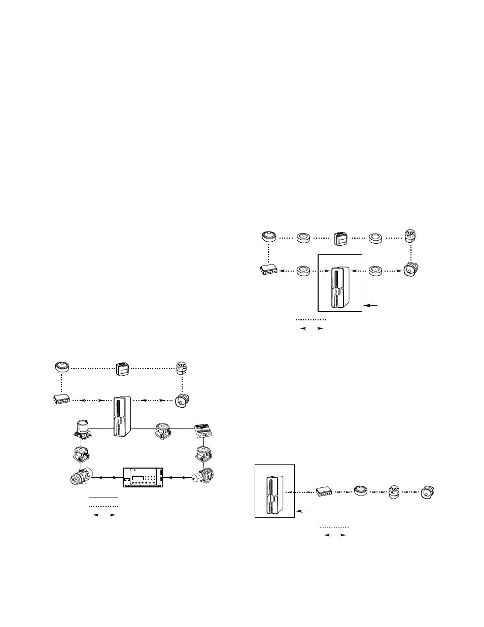
For the Class A wiring style, isolators are optional on the
ASH Module Apollo loop where only a single zone is
monitored. During a single open, a single ground fault,
or the combination of a single open and a single ground
fault, the Class A pathway shall maintain alarm receipt
capabilities. See Figure 2 for Class A pathway.
Class B requires that a spur configuration be used, with
the single spur connected to the “Loop Out” terminals on
the ASH Module. The Class B pathway is intended for
use in a single zone system. When a single ground fault
is present, alarm receipt capabilities shall be maintained.
Devices beyond a single open will lose connection, but
all devices will lose connection for a short. See Figure 3
for Class B pathway.
C2532
NODE 1
NODE 8
HARDWIRED LON CONNECTION
NODE 3
NODE 6
NODE 2
NODE 7
ASH MODULE
NODE 5
NODE 4
EQP
CONTROLLER
EAGLE QUANTUM PREMIER
Safety System Controller
Fire Alarm
Inhibit
Power
Supr
High Gas
Trouble
Cntrl Flt
Lon Fault
Low Gas
Ack
Silence
Out Inhibit
Eagle Quantum Premier
Time & Date
Cancel
Enter
Next
Previous
Reset
Acknowledge Silence
DET-TRONICS
®
NODE 64
NODE 1
...
NODE 63
NODE 3...
NODE 2
. . . . . . . . . . . . .
.......
........
ASH MODULE APOLLO LOOP
2-WAY COMMUNICATION
. . . . . . . . . . . . . . . . . . .
. . . . . . . . . . . . . . . . .
. . . . . . . . . . . . . . . . .
. . . . . . . . . . . . . . . . . . .
A2589
ASH MODULE
NODE 64
NODE 1
...
NODE 63
NODE 3...
NODE 2
SINGLE
ZONE
. . . . . . . . . . . . .
. . . . . . . . . . . . . . . . .
.......
........
ASH MODULE APOLLO LOOP
2-WAY COMMUNICATION
. . . . . . . . . . . . . . . . . . . . .
. . . . . . . . . . . . . . . . .
. . . . . . . . . . . . . . . . . . . . .
ISOLATOR
(Optional)
ISOLATOR
(Optional)
ISOLATOR
(Optional)
ISOLATOR
(Optional)
ENCLOSURE
Figure 1—EQP LON with ASH Module Communication
Figure 2—Class A Pathway (isolators are optional)
A2590
ASH MODULE
NODE 64
NODE 2...
...NODE 63
NODE 1
SINGLE
ZONE
. . . . . . . . . . . . .
. . . . . . . . . . . . .
ASH MODULE APOLLO LOOP
2-WAY COMMUNICATION
. . . . . . . .
. . . . . . . .
. . . . . . . .
ENCLOSURE
Figure 3—Class B Pathway (without isolators)