En g lis h – dB TECHNOLOGIES AC26N User Manual
Page 14
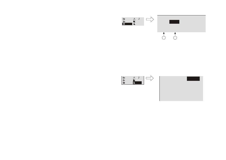
MENU DESCRIPTION - X-OVER
This window allows to select for each output a low pass filter, a high pass filter, or create a
band-pass filter via the combination of both.
The available filter is a Linkwitz-Riley, where it is possible to select slopes of 12 dB/oct, 24
dB/oct or 48 dB/oct and their cut-off frequency.
Ch. ob
Option
X-Over
Ch. ob
Option
X-Over
Meters
Preset
Matrix
Meters
Preset
Matrix
Type Freq
.
Type Freq
.
1
: HP12 106Hz Dis. --Hz
2
: HP24 329Hz LP24 732Hz
3
: HP48 216HZ LP48 74324Hz
Type Freq
.
Type Freq
.
1
2
3
: HP12 106Hz Dis. --Hz
: HP24 329Hz LP24 732Hz
: HP48 216HZ LP48 74324Hz
a
b
b
c
c
d
d
a) OUTPUT
CHANNELS
The output connectors are identified by the same information provided on the
screen printing located on the device rear side.
b) CROSSOVER
FILTER
Select the filter according to needs. It is possible to select:
Dis.
No filter enabled
HP
High-pass filter: set it to allow only the part of audio signal above the
cut-off frequency
LP
Low-pass filter: set to allow only the part of audio signal below the cut-
off frequency
Filter configuration
Low-pass High-pass
Nothing
Dis. Dis.
High-pass
HP
Dis.
Low-pass
Dis.
LP
Band-pass
HP
LP
12dB/oct
24dB/oct
Hz
dB
48dB/oct
12dB/oct
24dB/oct
frequency
frequency
frequency
frequency
Hz
dB
48dB/oct
c) ATTENUATION
SLOPE
Select the attenuation slope of the audio signal on
the basis of the desired attenuation.
The higher the attenuation slope, at the same cut-off
frequency, the greater the signal selection.
It is possible to select:
12
equal to 12 dB/oct
24
equal to 24 dB/oct
48
equal to 48 dB/oct
d) CUT-OFF
FREQUENCY
To set the passing frequency for the lower frequencies
only (low-pass filter) or the higher frequencies only
(high-pass filter).
The choice of the cut-off depends on the desired
sound reproduction
The unit of measurement used is Hz.
Hz
Hz
dB
dB
G
a
in
G
a
in
G
a
in
G
a
in
f0
f0
0dB
0dB
0dB
-6dB
-6dB
0dB
0dB
E
n
g
lis
h
26
E
n
g
lis
h
25
MENU DESCRIPTION - MATRIX
For each output, it allows to select the input signal to use as the source.
Ch. ob
X-Over
Option
Ch. ob
X-Over
Option
a) OUTPUT
CHANNELS
Identification of the output channel to set
b)
IDENTIFICATIONS OF THE INPUTS
It selects the type of signal to match each output, as needed. It is possible to select:
In A
Associated with the input signal “A”
In B
Associated with the input signal “B”
In A+B
Associated with the algebraic sum of the two input signals “A” and “B”
a
b
Meters
Preset
Matrix
Meters
Preset
Matrix
Channel Source Channel Source
Out 1:
Out 4: In B
Out 2: In B Out 5: In A+B
Out 3: In A+B Out 6: In B
In A
Channel Source Channel Source
Out 1:
Out 4: In B
Out 2: In B Out 5: In A+B
Out 3: In A+B Out 6: In B
In A
MENU DESCRIPTION - OPTION
Allows to display the system settings, such as the allocation of the inputs and outputs,
attenuation, display contrast and firmware version
Ch. ob
X-Over
Option
Ch. ob
X-Over
Meters
Preset
Matrix
Meters
Preset
Matrix
InA-B Src:
Dig.Out Src: An. In
Input Link:
Indip.
Atten. Pad:
0dB
An. In
InA-B Src:
Dig.Out Src: An. In
Input Link: Indip.
Atten. Pad:
0dB
An. In
Contrast:
60%
Fw. Vers.:
v
0
.7.11
Contrast:
60%
Fw. Vers.:
v
0
.7.11
InA-B Src
This option allows to set the type of input audio signal.
An. In
= Analog audio signals (inputs A and B)
Dig.In
= Digital audio signals (AES/EBU input)
Dig.Out Src
This option allows to select the audio source that will be forwarded to the connector
AES/EBU OUT (digital output)
An. In
= Audio signals available at analog inputs
Dig. In
= Audio signals available at digital inputs
OUT 1-2
= Audio signals available on outputs 1 and 2
OUT 3-4
= Audio signals available on outputs 3 and 4
OUT 5-6
= Audio signals available on outputs 5 and 6
Input Mode
It allows to configure the inputs.
Indip.
= They are independent, not subject to constraints of any kind between
them
Linked
= They are connected and work in stereo mode
Compressors, filters, delays, volume... are identical for the two channels