En g lis h, Push – dB TECHNOLOGIES AC26N User Manual
Page 11
Digital Audio Connections (AES/EBU)
AES/EBU (AES3 protocol) is and a balanced input, electrically insulated by means of a
transformer. It allows carrying two audio channels in a single two-wires shielded cable.
The cable characteristics are: twisted, 3 poles, impedance 100 ohm, shielded, equipped
with XLR connector (AES3 standard)
RDnet
Each RDNet port on Control 2 and Control 8 can be connected to maximum 32 cascade-
connected compatible devices.
In the example below, the control unit RDNET CONTROL 2 port is connected to the DATA
INPUT of an AC 26N, whose parallel DATA LINK output is sent to the input of the next
AC26N.
In the example, [n] is a number between 3 and 32 (maximum limit for the devices
connected to a sub-network)
RJ 45
|1|2|3|4|5|6|7|8|
The overall length of a CAT5 sub-network cable cannot exceed 900 meters.
The connector must be connected as follows:
1 -
Available for other functions (for example: audio +)
2 -
Available for other functions (for example: audio -)
3 -
Available for other functions (for example: analog ground)
4 -
digital ground
5 -
digital ground
6 -
Available for other functions (for example: power supply)
7 -
RS 485 A
8 -
RS 485 B
Data
Link
ACTIVE
ON
Data
Input
PUSH
PUSH
Data
Link
ACTIVE
ON
Data
Input
PUSH
PUSH
Data
Link
ACTIVE
ON
Data
Input
PUSH
PUSH
CH 1
RDNET
CONTROL 2
AC26N [1]
AC26N [2]
AC26N [n]
PUSH
POWER ON
When the device is turned on, the initialization procedure starts. It lasts few seconds. The
display shows the device model, the company logo and a program loading progress bar.
At the end of the installation process the display shows the Meters menu. For further details
about the indications, refer to the paragraph MENU DESCRIPTION - METERS.
AC26N is now ready for use
Local
Local
0
TECHNOLOGIES
TECHNOLOGIES
RDNET
AC26N
V 0.7.1
A B
1 2
3 4
5 6
CONFIGURATION AND DISPLAY
To access the main menu window, press the MENU key located on the device front panel.
In any page of the menu, press the ESC button to return to the previous screen
MAIN MENU
Ch. ob
X-Over
Option
Ch. ob
X-Over
Option
Meters
Preset
Matrix
Meters
Preset
Matrix
There are six menus in the processor. They show and/or configure the system parameters.
The main menus are:
Meters
Input and output levels display; program in progress display, quick
muting
Preset
Store, save, and delete the system configurations
Matrix
Select the outputs according to the input signal
Ch. Job
Configuration of each individual channel
X-Over
Configuration of the cut-off frequency and the types of filters for each
output
Option
Assignment of the inputs and outputs, display contrast, firmware version,
inputs and other options
E
n
g
lis
h
20
E
n
g
lis
h
19
The menus and the individual options displayed can be selected by rotating the knob
“FUNCTION SELECTOR” ( ) .
To access the selection, highlight the desired parameter and press the “Push Enter” ( | )
knob.
The same procedure should be adoptd to select and/or change the options inside each
menu entry.
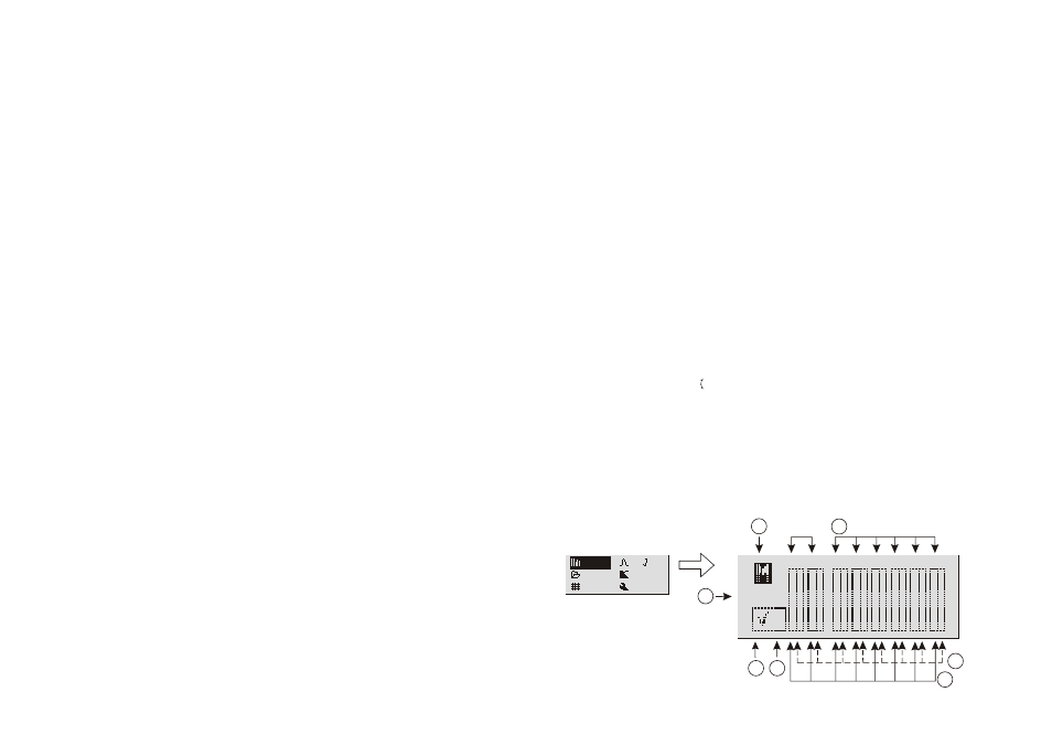
MENU DESCRIPTION - “Meters”
This window allows to view the configuration and the general conditions of the inputs and
outputs, the version of the program used, the program status and how the system is driven.
INGRESSI
USCITE
b
e
a
c
f
d
g
Ch. ob
X-Over
Option
Ch. ob
X-Over
Option
Meters
Preset
Matrix
Meters
Preset
Matrix
Local
Local
0
A B
1 2
3 4
5 6