Equipment set up, Installation of the mechanical sensing unit – Condux Running Line Tensiometer User Manual
Page 9
9
Equipment Set Up
Installation of the Mechanical Sensing Unit
The Mechanical Sensing Unit is designed to mount directly to the frame of Condux
CableGlider® cable pullers. Two distinct mounting mechanisms are used for three cable puller
models. Be aware of which model of CableGlider that your tensiometer is to be used with
(CableGlider STD, HD, and Plus) and follow the specific instructions for the model. The
Mechanical Sensing Unit can also be used with other rope capstan cable pullers; however,
mounting will vary.
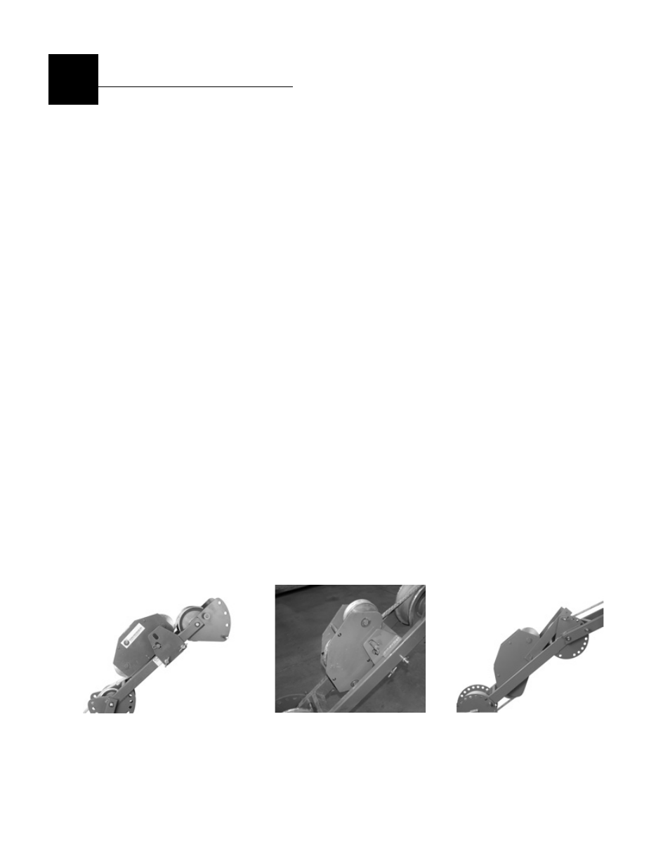
INSTALLATION ON CABLEGLIDER STD
Attach the Mechanical Sensing Unit to the CableGlider STD model using a mounting bracket
over the frame of the upper arm of the cable puller and pin to hold in place (See Figure 1). The
Mechanical Sensing Unit attaches to the mounting bracket with one pin.
INSTALLATION ON CABLEGLIDER PLUS
Attach the Mechanical Sensing Unit to the CableGlider Plus model using a mounting bracket
between the frame of the first arm of the cable puller and pin to hold in place (See Figure 2). The
Mechanical Sensing Unit attaches to the mounting bracket with one pin
INSTALLATION ON CABLEGLIDER HD
Attach the Mechanical Sensing Unit to the CableGlider HD model by using a mounting arm
(included) and two pins (included). Pin the support arm to the Mechanical Sensing unit. Mount
this assembly to the cable pullers midsection adjustment plate. (See Figures 3).
INSTALLATION ON OTHER ROPE CAPSTAN PULLERS
Securely fix the mechanical sensing unit to the cable puller frame to prevent the unit from
“walking with the rope” Approximately 200 pounds (900 N) of force will be required to hold the
mechanical sensing unit in place.
3
Figure 1 STD Puller
Figure 3 HD Puller
Figure 2 PLUS Puller