25
Bottom Connections
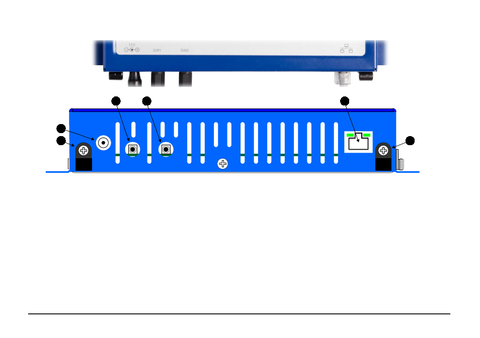
Figure 7 - Bottom View of RF500A Gateway
A.
Cable clamps
B.
12 VDC input
C.
SW1 – Jack Socket for Relay Output 1
D.
SW2 – Jack Socket for Relay Output 2
E.
RJ45 Ethernet LAN Socket
E
D
C
B
A