20ma transmitter and dcs connections, Fisher-rosemount model 275 handheld hart terminal, 20ma transmitter and dcs connections -2 – CiDRA SONARtrac Quick Start User Manual
Page 22: Figure 4, Transmitter connector board 4-20ma connections -2, Figure 5, Figure 6, Sonartrac transmitter and hart 275 communicator -2
4.2.2
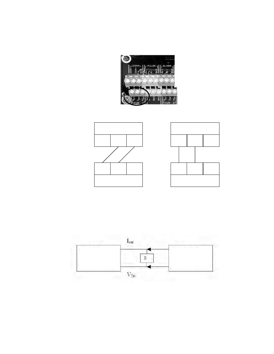
4-20mA Transmitter and DCS Connections
Connect to the appropriate terminals on the transmitter connector
board.
Figure 4
Transmitter Connector Board 4-20mA Connections
SONARtrac transmitter
SONARtrac transmitter
(Internal 4-20mA)
(External 4-20mA)
V
EXT
V
EXT
I
OUT
V
INT
I
OUT
V
INT
SONARtrac
Transmitter
HART 275
Communicator
Figure 5
Transmitter to DCS Wiring for Internal and External Power Select
4.2.3
Fisher-Rosemount Model 275 Handheld HART Terminal
The polarity is unimportant for the Model 275; however, the
SONARtrac power select MUST be Internal. The value of R must be
250 ohms.
Figure 6
SONARtrac Transmitter and HART 275 Communicator
Plant DCS
-
+
Plant DCS
+
-
Copyright © 2007 CiDRA Corporation
Page 4-2
20984-01 Rev 01