2 3 7 controller – C.B.S. Scientific DGGEK-4801 User Manual
Page 7
12
13
www.cbsscientific.com
Cipher DGGE Instructions 2/28/14
2 3 4 h Local Lockout Feature
This feature enables the user to lock all controls on the controller. While the feature is acti-
vated, the unit will remain running at the current settings. To activate the local lockout feature,
press and hold the Select/Set Knob for 10 seconds. Once locked, the screen will read LLo.
When locked, the setpoint decimal point will not flash as usual. Press and hold the Select/Set
Knob again for 10 seconds to unlock the controls. Once unlocked, the screen will read CAn.
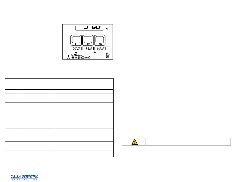
2 3 4 i Stick-on Strips for Preset Buttons
The Standard Controller is supplied with two
stick-on strips that can be applied beneath the
Preset Buttons. These strips are removable and
can be reapplied. The user can write the set
point temperature associated with each Preset
Button on this strip. The use of an erasable
medium, such as dry erase marker or flair tip
pen is recommended. The former can be wiped
off with a dry cloth or tissue; the later can usu-
ally be removed with simple glass cleaner and a
cloth or tissue. Do not use a permanent marker
or ballpoint pen. Always do an ink test before
writing on these strips.
2 3 5
Controller Display Messages
The stick-on strip fits beneath the controller’s
Preset Buttons. It is removable and reapplicable.
Display
Description
Action Required
….
Standby mode
Normal — Indicates that the Circuit Breaker/Power Switch is ON
and the Controller Power Switch is OFF
tx.xx
Power up self-test
Normal — Appears momentarily at startup
oCx.x
Calibration offset value
Normal — Current calibration offset value; refer to section 6.1
Hxxx
Software High Limit value
Normal — Current Software High Limit value; refer to section 5.6
Axxx
Auto-Refrigeration set point value
Normal — Current Auto-Refrigeration set point; refer to section
5.10 (Appears only on Refrigerating/Heating Circulators)
E-H1
Software High Limit set point too low
Error — The value entered is below the control temperature set
point. Refer to Setting Software High Limit, section 5.6
FLt 1
Software High Limit value exceeded
Error — Set a Software High Limit value higher, then turn main
power to the unit OFF and back ON; refer to section 5.6
FLt 2
EEPROM reset
Error — Turn Circuit Breaker/Power Switch OFF, hold P3 Button,
and then turn the Circuit Breaker/Power Switch back ON
FLt 3
Safety Set temperature exceeded
Error — Check fluid level
Check fluid temperature and set point
Ensure that OTP set point is higher than fluid set point or
increase to maximum
Turn Circuit Breaker/Power Switch OFF, press Safety Set Reset
Button, and then turn the Circuit Breaker/Power Switch back ON
FLt 4
Heating Triac failure
Error — Service required
FLt 5
Probe failure
Error — Service required
FLt 6
i2c error — Communication failure to
modulation board
Error — Service required (Appears only on Refrigerating/Heating
Circulators)
Calibration allows the user to match the Controller’s bath temperature display to an external
reference thermometer. Calibration is performed as follows:
Set the desired operating fluid temperature set point and allow temperature to stabilize.
Press the P2 and P3 simultaneously and release and repeat until the display reads (oCx.x). Press
P1 and hold until (Cal) is displayed. This will take about 2 seconds.
At one second intervals, the displayed value will alternate between the actual bath fluid temperature
and the current offset value, which is the difference between the factory calibration setting and the
user’s reference temperature sensor. The maximum offset is ±0.9°C from factory calibration.
To change the calibration offset value, rotate the Select/Set Knob until the display matches the
reading on the reference temperature sensor. The display will continue to alternate between the
offset value and the calibrated display temperature.
Press the Select/Set Knob or the P1 Button to accept the entered value. When the new calibration is
stored and the mode is exited, (dONE) will appear on the display.
NOTE: The displayed offset value will also be accepted if there no activity for 20 seconds.
The heater should be kept clean. If deposits build up on the heater, they may be removed by
scrubbing with a non-metallic (plastic) abrasive pad. Do not use steel wool.
2 3 6
Controller Calibrations and Maintenance
2.
3.6.a Calibration
Calibration allows the user to match the Controller’s bath temperature display to an external
reference thermometer. Calibration is performed as follows: Set the desired operating fluid tem-
perature set point and allow temperature to stabilize. Press the P2 and P3 simultaneously and
release and repeat until the display reads (oCx.x). Press P1 and hold until (Cal) is displayed. This
will take about 2 seconds. At one second intervals, the displayed value will alternate between
the actual bath fluid temperature and the current offset value, which is the difference between
the factory calibration setting and the user’s reference temperature sensor. The maximum offset
is ±0.9°C from factory calibration. To change the calibration offset value, rotate the Select/Set
Knob until the display matches the reading on the reference temperature sensor. The display
will continue to alternate between the offset value and the calibrated display temperature. Press
the Select/Set Knob or the P1 Button to accept the entered value. When the new calibration is
stored and the mode is exited, (dONE) will appear on the display. NOTE: The displayed offset
value will also be accepted if there no activity for 20 seconds. 6.2 Heater The heater should be
kept clean. If deposits build up on the heater, they may be removed by scrubbing with a non-
metallic (plastic) abrasive pad. Do not use steel wool.
2.3.6.b Pump Motor
The pump bearings are permanently lubricated with high-temperature silicone grease and do not
require additional lubrication. Should the bearings become noisy, replacement of the entire pump
motor is recommended. This will reduce repair labor costs and retain fluid pumping reliability. A
replacement pump and motor mounting kit is available (see Section 10 - Replacement Parts). 6.4
Cleaning Only mild detergents and water or an approved cleaner should be used on the painted
and stainless steel surfaces of the Circulator. Do not allow cleaning liquids or sprays to enter the
Controller vents. A concentrated bath cleaner is available that can be used to remove mineral
deposits from the reservoir. See Section 10 - Replacement Parts.
2 3 7 Controller
Reservoir Fluids
For your buffers use distilled or RO water only!
DO NOT USE the following fluids:
1. Automotive antifreeze with additives**
2. Hard tap water**
3. Deionized water with a specific resistance > 1 meg ohm
4. Any flammable fluids
5. Concentrations of acids or bases
6. Solutions with halides: chlorides, fluorides, bromides, iodides or sulfur
7. Bleach (Sodium Hypochlorite)
8. Solutions with chromates or chromium salts
9. Glycerine
10. Syltherm fluids
** At temperatures above 40°C, additives or mineral deposits can adhere to the heater. If
deposits are allowed to build up, the heater may overheat and fail. Higher temperatures
and higher concentrations of additives will hasten deposit build up
Warning: Do not use a flammable liquid as a bath medium as a fire hazard
may result.