C.B.S. Scientific DGGEK-4801 User Manual
Page 6
10
11
www.cbsscientific.com
Cipher DGGE Instructions 2/28/14
2 3 4
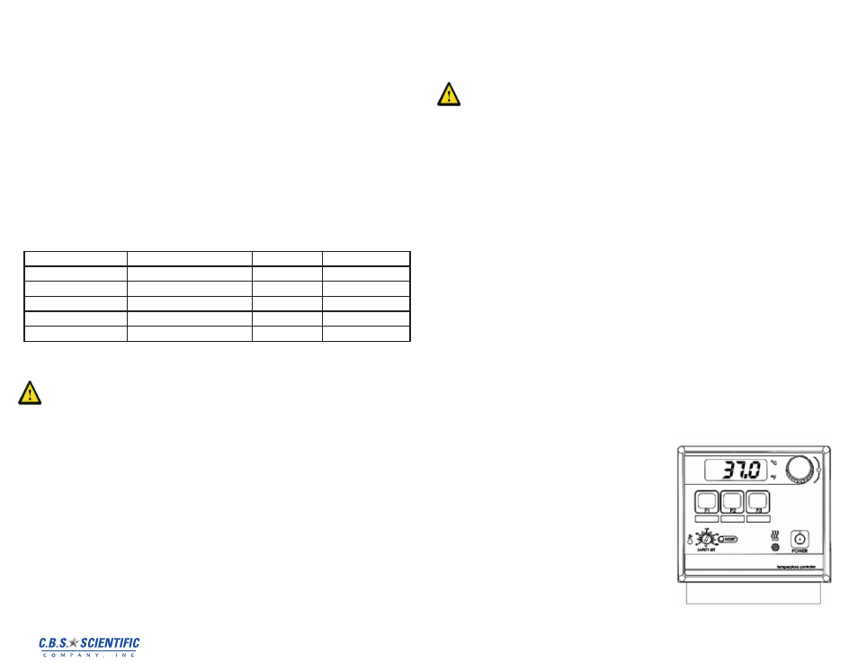
Controller Operation
2
3 4 a Reservoir Liquid Level
Fill the reservoir with the appropriate buffer. The DGGEK Systems are designed to be used
with reagent buffers such as 1xTAE or 1xTBE. On Circulating Baths, the liquid level should
be sufficient to cover the heating coils, pump, over-temperature sensor, and at least one inch
(25mm) of the temperature sensor. On Immersion Circulators, the liquid level should be suf-
ficient to fully immerse the heater coils, over-temperature sensor, and pump outlet nozzle.
2 3 4 b Power
An IEC power cord is provided with the Circulator. This power cord should be plugged into
the IEC receptacle on the rear of the Controller and then plugged into a properly grounded
outlet. Make sure that the power outlet is the same voltage and frequency indicated on the
identification label on the back of the Controller. The use of an extension cord is not recom-
mended. However, if one is necessary, it must be properly grounded and capable of handling
the total wattage of the unit. The extension cord must not cause more than a 10% drop
in voltage to the Circulator. Once the unit has been connected to an appropriate electrical
outlet, place the Circuit Breaker/Power Switch on the rear of the Controller in the ON position.
Four decimal points (….) will appear on the digital display. DO NOT place the Power Switch
on the front of the Controller ON until the Safety Set has been adjusted to the desired tem-
perature (see 3.6 below).
Indicated Voltage:
Volts/Phase/Frequency
Operational Voltage Range
Phase
Frequency
100/ 1 / 60
90 to 110 Volts
single
60 Hz
100/ 1 / 50
90 to 110 Volts
single
50 Hz
120/ 1 / 60
110 to 130 Volts
single
60 Hz
230/ 1 / 60
208 to 230 Volts
single
60 Hz
240/ 1 / 50
220 to 240 Volts
single
50 Hz
2 3 4 c Setting the Safety Set Set Point -
NOTE: DGGEK is factory set to 80ºC
The Safety Set feature automatically disconnects Controller power to the heater and pump in
the event that the reservoir liquid level drops too low or the Controller fails. The Safety Set is
user-adjustable between approximately 40° and 210°C. It should be set at least 5°C higher
than the Software High Limit temperature. Use a flat blade screwdriver to rotate the Safety
Set Indicator Knob to the desired temperature. Do not force the knob beyond the stops at ei-
ther end of the temperature value range. Once the Safety Set temperature has been set, turn
power to the Controller ON by pressing the Power Switch on the front of the Controller. The
pump will begin operating, the display will flash the current temperature set point (tx.xx), the
°C LED will light, and the current bath temperature will appear on this display. Pump speed
selection is made using the Pump Speed Selection Switch on the rear of the Controller (see
Section 2.3 or 3.3). If power is disrupted because the Safety Set temperature was exceeded,
place the Circuit Breaker/Power Switch in the OFF position, press the Safety Set Reset But-
ton, correct the problem (low liquid level, incorrect Safety Set temperature, etc.), and then
restore power. Activation of the Safety Set during normal operation will display a fault (FLt 3)
on the readout.
2 3 4 d Selecting Temperature Units
The control set point and actual bath temperatures may be displayed in either °C or °F. The
factory-default is °C. To change from °C to °F, place the Circuit Breaker/Power Switch on the
rear of the Controller in the OFF position and then press and hold the P2 Button while turning
the power back ON.
To change from °F to °C, place the Circuit Breaker/Power Switch in the OFF position and then
press and hold the P3 Button while turning the power back ON.
NOTE: When the temperature display units are changed, the Software High Limit value and all
temperature presets revert to the factory-default values. If a calibration value has been entered,
the value will be retained.
2 3 4 e Setting the Software High Limit -
NOTE: DGGEK is factory set to 75ºC
This feature provides additional safety and protection by allowing a selectable upper tem-
perature limit set point. To avoid an unwanted shutdown during regular operation, the high
limit value should be set at least 5°C higher than the selected control temperature To set the
Software High Limit temperature set point, press the P2 and P3 keys simultaneously and repeat
until (Hxxx) appears on the display. This is the current Software High Limit value. It is factory set
at 75°C. To change the displayed value, press and turn the Select/Set Knob until the desired
Software High Limit set point value is displayed. A clockwise rotation increases the value; a
counterclockwise rotation decreases the value. Press the Select/Set Knob a second time to
accept the new value and return to normal operation. If the Software High Limit value meets or
exceeds the control temperature set point, (E-H1) will flash on the display. If this occurs, enter
a higher value for the Software High Limit or reduce the control temperature set point. If the
actual bath temperature reaches the Software High Limit setpoint, (FLt1) will flash on the dis-
play. Should this occur, the Controller will automatically remove power from the heater and, in
Refrigerating/Heating units, the compressor as well. The pump will continue to operate. Once
the problem is corrected (bath temperature reduced or Software High Limit value increased),
press the Power button to clear the message.
2 3 4 f Setting the Set Point Temperature
Press and release the Select/Set Knob. The decimal point flashes to indicate that the set point
temperature can be changed. Turn the Select/Set Knob until the desired temperature set point
is displayed. A clockwise rotation increases the setting; a counterclockwise rotation decreases
the setting. Press the Select/Set Knob a second time to accept the displayed value. The deci-
mal point stops flashing and the display will indicate the actual bath temperature. Allow suf-
ficient time for the bath to stabilize at the desired temperature before making any adjustments
to set point temperature. NOTE: The unit will automatically accept the displayed set point after
approximately 10 seconds of inactivity, even if the Select/Set Knob was not pressed. The set
point temperature may be checked at any time by pressing the Select/Set Knob. If the set
point temperature cannot be raised, it is possible that the Software High Limit value is set lower
than the desired control temperature set point. Reset the Software High Limit value to 5°C or
more above the desired set point temperature.
2.3.4.g User-Definied Preset Temperatures
With the unit on, press the desired Preset Button —
P1, P2, or P3. The LED associated with the selected
Preset Button will begin to flash. Rotate the Select/
Set Knob to the desired temperature set point. Press
the selected Preset Button a second time to enter the
new set point. The new set point temperature will not
be saved unless the Preset Button is pressed. The
LED associated with Preset Button lights continu-
ously whenever that preset value is controlling bath
temperature. If more than one Preset Button is set
at a given temperature set point, the LED associated
with all Preset Buttons with that set point will light.