Dggek-2001 – C.B.S. Scientific DGGEK-4801 User Manual
Page 4
6
7
www.cbsscientific.com
Cipher DGGE Instructions 2/28/14
1.3
Safety
Power to the DGGE systems is to be supplied by an external DC voltage power supply
that must be ground isolated so that the DC voltage output floats with respect to
ground. For any power supply used, the maximum specified operating parameters for
the units are:
Maximum Limits
250 VDC voltage
30
watts
power
80
mA
current
70°C ambient temperature
Current to the unit, provided from the external power supply, must enter the unit
through the lid assembly, providing a safety interlock to the user. DC current to the unit
is broken when the lid is opened.
Do not attempt to use the unit without the safety
lid. Always turn the power supply off before removing the lid, or when working
with the unit in any way. Follow safety precautions specified by the power supply
manufacturer.
Input Power: Mains to safety interlock
Depending on country of destination, input voltage from mains electrical supply are as
follows: 110-120VAC @ 50/60Hz/5 Amps or 200-240VAC @ 50/60Hz/5 Amps. Country
specific power cords or CE approved adapter kits are supplied with each system.
Warning: Do NOT turn on Heater/Stirrer until tank has been filled with buffer!
SECTION 2
DGGEK Unit Set-Up
2 1 Unpacking Instructions
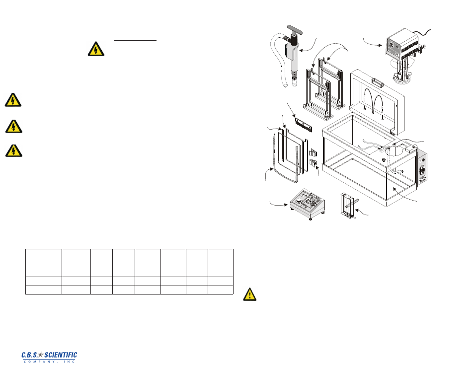
1) Unpack the DGGE Tank Assembly and place on level surface in an approved location.
Using figure 2-1 verify that your DGGEK-4001 or DGGEK-4801 System comes
complete with the following components:
• EPS-300 X Power Supply (not pictured)
• Peristaltic Mini-Pump for gel casting
• Lower Reservoir/Acrylic tank/safety interlock/ with 2 black leads inside lid
• Heater/Stirrer/By-pass pump (Controller) - factory-mounted onto DGGE tank
• Gel cassette(s), combs, spacer sets, Gel Wrap
™
gaskets, and glass plates sets as
specified in chart below:
• 1 Gradient maker, 20mls per side, Cat. # GM-40
• White spring clamps
• Buffer siphon pump with tubing, Cat# BSP-1000
• 2 Conversion Plates (not shown) for running 1 gel at a time on dual cassette (for
DGGEK-4801 only)
Figure 2-1
Heater
Stirrer
Buffer Siphon
Pump Assembly
Vapor
Shield
Thermometer
DGGE
Tank
Single
Cassetes
Comb (2)
Spacers
(2 pairs)
Glass Plate
Assembly(2)
Clamps
Mini-Pump
(Optional)
GM-40
Gelwrap
® (2)
Buffer recycling
manifold
2. Open the lid and confirm the following:
a) Two lengths of small bore silicone tubing for buffer cycling are already attached
to the buffer recycling manifold outlets
b) A single length of large bore tubing from the By-Pass Pump is connected to the
barb-fitting on the plastic manifold.
DGGEK-2001
2 2 Filling DGGE tank with Buffer
1) Fill the tank with running buffer (see Section 6 for buffer formulations) to minimum
level. This requires 32 liters of buffer.
Use distilled or RO water when making
buffer
Type of Gel
Cassette(s)
# of
Sample
Well
Combs
# of
1-well
Combs
# of Gel
Wrap ™
Spacer
Sets
# of Per-
pendicular
Spacer
Sets
# Gel
Wrap™
Gaskets
# glass
Plate Sets
DGGEK-4001
4 single
4
4
4
4
8
4
DGGEK-4801
4 dual
8
8
8
8
16
8