Lighting mode, Gauge reset, Data logger output – Auto Meter 5640 User Manual
Page 3: Pro control active states
Lighting Mode
(Region B Color)
This gauge allows the dial lighting to operate in two modes, Full On or Dimmable. Factory default is Full On.
full On:
In this mode, the white lighting wire is ignored. The gauge dial lighting is always on at full brightness. (unless you select NO color
when setting the Backlight Color). If using Full On mode, white wire hook-up is not needed.
dimmable: In this mode, the white wire is used to set the intensity of the dial lighting from full brightness down to off.
To change the Lighting Mode:
With power off, press and hold the pEAK button. Apply power to the gauge. Release the pEAK button and the dial face will illuminate with
either white lighting or blue lighting. Press and release the PEAK button to toggle between Full On (dial is illuminated white) and Dimmable
(dial is illuminated blue). Once you have selected the desired mode, don’t press any buttons for about three seconds. The dial will flicker white
several times to indicate the desired setting has been saved and the gauge will return to normal operation with your new mode selection. Mode
selections are saved when power is off.
NOTE: The Pro Control Active State does not
affect the color of each dial region.
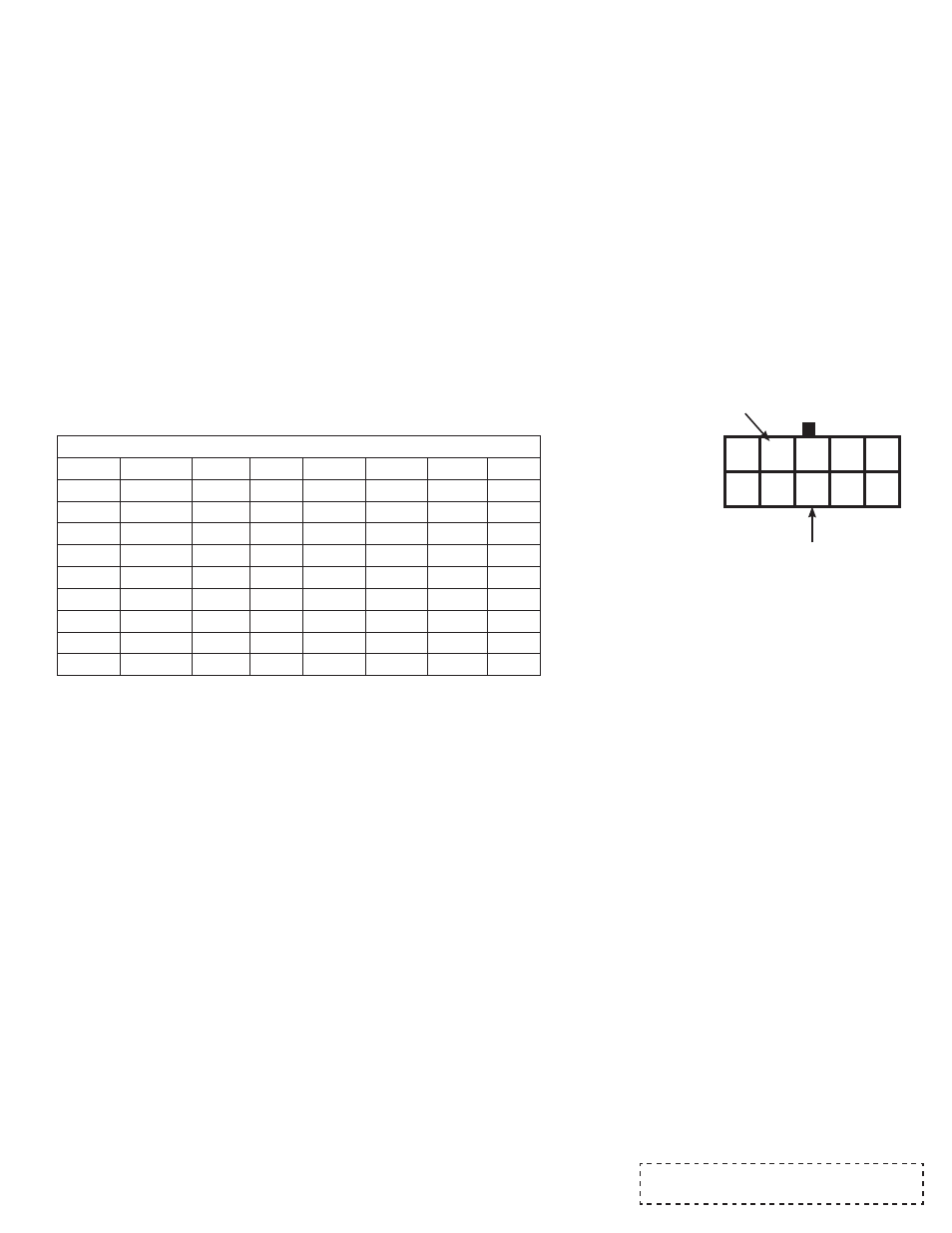
(Back of Gauge)
Ground Neg (-)
(Black)
Sensor Signal (+)
(Yellow)
5 4 3 2 1
10 9 8 7 6
It may be desired to reset the gauge. This clears programmable
settings to a system default. With power off, hold in both buttons.
Apply power to the gauge, wait two seconds, and release both buttons.
The dial face will flicker white several times and return to normal
operation. At this point, the gauge has been reset.
Reset Settings:
High Warning Set Point: Max Value
Low Warning Set Point: Lowest Value
Peak: Lowest Value
High Warning Color: Red
Low Warning Color: Green
Backlighting Color: White
Lighting Mode: Full On
High Warning Pro Control State: Active High
Low Warning Pro Control State: Active Low
High Over Warn Set Point: Max Value
Low Over Warn Set Point: Lowest Value
The active region for Pro Control outputs are user configurable. For
example, consider a pressure gauge with a low warning set point at
20 PSI . The gauge can be configured so the associated Pro Control
output is active when the pointer falls below the set point [less than 20
PSI] (active low) OR when the pointer is beyond the set point [greater
than 20 PSI] (active high). Likewise, consider a pressure gauge with
high warning set point at 95 PSI. Again, the gauge can be configured
so the associated Pro Control is active when the pointer falls below
the set point [less than 95 PSI] (active low) OR when the pointer
progresses beyond the set point [greater than 95 PSI] (active high).
To change the active state:
With power off, press and hold the pEAK button. Apply power to the
gauge. Release the pEAK button. Press and release the wARN
button. The gauge is now in Active State Set Mode. The pointer will
point straight up at the value in the top center of the dial. Press and
release the wARN button to toggle back and forth between the low and
high warning point active state modes. Doing so will cause the dial to
change back and forth between green and red. When setting the low
warning active state the dial face will be green. When setting the high
warning active state the dial face will be red.
Once the designated warning mode is selected (green or red) press and
hold the wARN button to toggle between active high and active low. As
you hold the button the pointer will continuously sweep from the left of
center and to the right of center pausing at each side. Left of center is
active low and right of center is active high. Release the wARN button
when the pointer is in the position of the desired active state. Once you
have selected the desired state, don’t press any buttons for about three
seconds. The dial will flicker white several times to indicate the desired
setting has been saved and the gauge will return to normal operation
with your new state selection. State selections are saved when power is
off.
gauge Reset
Data Logger CaLibration Chart
Temp (F)
DL Vout
N
Temp (F) DL Vout
N
Point 1
60
0.510
418
Point 10
200
3.333
2730
Point 2
80
0.791
648
Point 11
220
3.662
3000
Point 3
100
1.174
962
Point 12
240
3.937
3225
Point 4
120
1.594
1306
Point 13
250
4.056
3323
Point 5
130
1.810
1483
Point 14
260
4.155
3404
Point 6
140
2.030
1663
Point 15
280
4.342
3557
Point 7
160
2.507
2054
Point 16
310
4.535
3715
Point 8
180
2.938
2407
Point 17
340
4.668
3824
Point 9
190
3.145
2576
data Logger Output
This gauge is equipped to output the sensor signal to an external data logger system. This feature allows you to use the same sensor for both the
gauge and the data logger. With this gauge, it is not necessary to install two sensors to measure the same function.
To use this feature, you must have a data logger system installed in the vehicle and connect the data logger output from the gauge to the data
logger. Pins number 4 (black wire, ground) and 8 (yellow wire, sender signal) in the connector on the back of the gauge are the data logger sensor
signal and ground connections that must be connected to the data logger. After connecting the gauge to the data logger, refer to your data logger
instruction on how to calibrate the data logger to use the signal.
Quick Calibration:
Use the voltage in the ‘DL Vout’ column to calibrate your data logger over the desired temp range.
Calibration For More Accuracy:
Follow these steps to obtain a more accurate calibration.
On the side of the gauge is a label that reads ‘Data
Logger = x.xxx’ where x.xxx is a number.
This number is Vs in the following equation.
DL Vout = N x Vs / 4096
pro Control Active States