Auto Meter 6597 User Manual
Digital, Tach, Configuration
INSTALLATION INSTRUCTIONS
DIGITAL
™
TACH
2650-1222-00
Configuration
The tachometer is configured at the factory for 4 PPR. (8 CYL)
To change the PPR, follow the steps below:
QUESTIONS
:
If after completely reading these instructions you have questions regarding the operation or installation of your instrument(s),
please contact Auto Meter Technical Service at
815-899-0801.
You may also email us at
Additional information can also be found at
http://www.autometer.com/tech_faq.aspx
ENGINE
Most
Most
Most
Most
2 cyl.
4 cyl.
6 cyl.
8 cyl.
PPR
1
2
3
4
4. When the display indicates the desired PPR, press and hold the RIGHT “-” button for 1 second,
then release. This will permanently store the settings and exit Configuration mode.
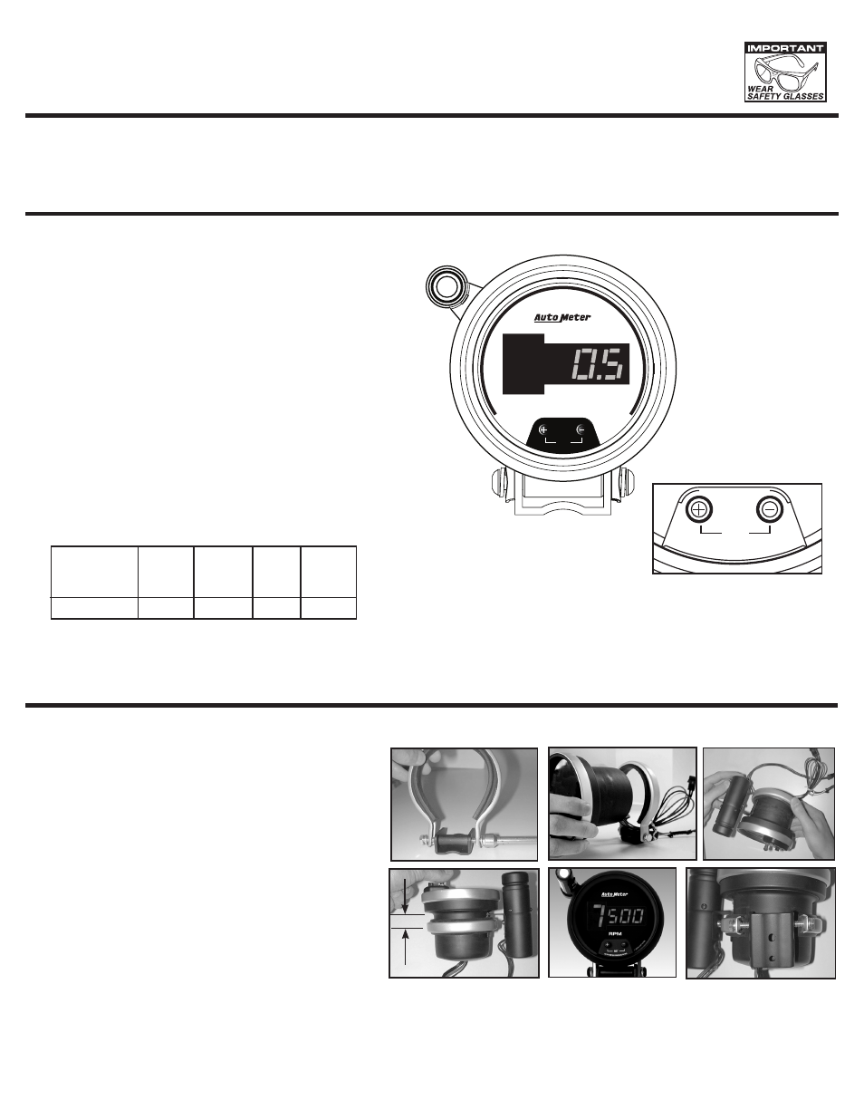
1. With no power applied to the tach, press and hold the
RIGHT “-” button.
2. While holding the “-” button, apply power to the tach by
turning the ignition switch to the “Accessory” or “On” position.
Do not start the engine! Release the RIGHT “-” button.
The display will show 0.5.
3. The display will change every 1.25 seconds to 1.0, then 1.5,
2.0, 2.5, 3.0, 3.5, 4.0, 4.5, 5.0, 5.5, 6.0, and back to 0.5.
See the table below to find the display reading that
corresponds to the desired PPR.
RPM
© 2
006
-65
99
/65
97
AUTO METE
R PRODUCTS,
INC.
SET
Mounting for Pedestal Tachs
1) Loosen both bolts holding the shock strap to the mounting
foot. Back both bolts (
5
⁄
32
” allen wrench)
out until each is only
one or two turns into the spacer.
2) Pass tach wires through shock strap assembly and slide tach
casing into shock strap assembly.
3) Position Shift-Lite mounting bracket under shock strap as
shown in image. Adjust Shift-Lite, tach, and mounting base to
desired positions (see figure 4 for recommended shock strap
position), and tighten bolts (
5
⁄
32
” allen wrench)
holding mounting
foot to shock strap to secure the assembly.
4) Make sure rubber section of shock strap seats properly to
ensure proper fitment. Check to make sure shock strap is
approximately
3
⁄
4
”
(0.750”) between center line of strap and
step of tachometer casing for best mounting. Plug shift light
into tachometer connector. Plug is directional, do not force fit!
5) Recommended placement of external Shift-Lite is at 10
o’clock position. It is possible to place Shift-Lite in other
positions in accordance with driver preference and vehicle
mounting requirements.
6) The special design of the tachometer base allows for a variety
of mounting possibilities. Attach the base using screws
provided or use a pop rivet tool.
1)
2)
3)
6)
3
⁄
4
”
Note: Installation images shown may be different from your actual model.
5)
THOUSANDS
AUTO METER PRODUCTS INC
.
©
20
05
-49
90
®
RPM
10
0
2
3
4 5 6
7
8
9
1
SET
4)
Innovative E•Z VIEW™ DISPLAY SYSTEM
• Maximizes readability
• Minimizes distracting High Speed digit changes