Mounting, Wiring, Models – Auto Meter 6388 User Manual
Page 2: Caution
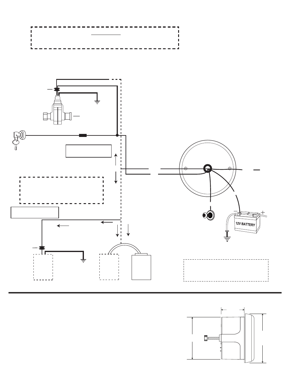
Mounting
1. Mount this instrument in a 3
3
/
8
" dia. hole.
2. Cut a
3
/
8
" dia. hole in the firewall for the speedometer wires. Place a rubber grommet
in the hole and route the wires through the grommet to the engine compartment.
3. Connect the speedometer wires as shown in the wiring sections.
4. Secure the speedometer to the dashboard using the provided bracket and hardware.
3
3
/
8
" Models
2
1
/
8
"
3¾
"
3
11
/
32
"
Wiring
Auto Meter Hall-Effect senders (Square Wave)
- Models 5291 (standard 7/8-18 thread) & 5292
(Ford Plug in Sensor), 3 wire sender, cruise.
Remove cap for cruise
control cable, otherwise
leave cap installed.
GND
FUSE
(SEE CAUTION)
Red
Violet
Orange
Black
White
3-Wire Sender
12V
IGNITION
SWITCH
Back of
speedometer
GND
12V DASH
LIGHTING
Dims Digital Display
When Power is Applied.
Sine
Wave
2 Wire
Sender
Sine
Wave
2 Wire
Sender
V.S.S.
PCM,
ECM,
COMPUTER
IF NO
COMPUTER
COMPUTER
CONTROLLED,
TAP ONTO
HI-SIDE V.S.S.
SIGNAL
Good Engine Ground
VSS to ECM
(see Note)
GROMMET
GROMMET
GND
LO
HI
BLACK
HI
OR
IF
LO
(OR)
NOTE: The speedometer signal output terminal (VSS)
produces a +5 volt DC Square wave signal.
This signal may be able to be used as a VSS
signal with some OEM and aftermarket ECM’s
and cruise control units.
CAUTION!
As a safety precaution, the power wire to this product should be fused before
connecting it to the positive (+) side of the 12 VDC battery. We recommend using a
1 Amp fuse.
Use 20 AWG stranded or
heavier wire for hook-up
Most OEM style or Factory Installed,
2 wire senders (Sine Wave)
IMPORTANT
When using most OEM/factory installed
(2 wire) senders, you must calibrate the
speedometer before it will function properly.
Use 20 AWG stranded or
heavier wire for hook-up