Auto Meter 2329 User Manual
Gauge console, Preliminary steps, Oil pressure
INSTALLATION INSTRUCTIONS
2
5
/
8
” 3-GAUGe CONSOLe
MODeL 2328, 2329, 2398, 2399
®
2650-316X-10
Rev. G
by
Preliminary Steps
1. Read instructions thoroughly. The installation of this product
requires the expertise of a trained automotive mechanic. Please
consult a qualified mechanic if you have not had training in the
proper installation of instruments.
2. Determine ideal mounting location. Choose a location that will not
obstruct visibility or impair driving. Consult your vehicle’s repair
manual to locate:
A. Water temperature port
B. 12V ignition switch or fuse box
C. Oil pressure port
3. Consult your vehicle’s manual to determine the best route for
tubing to follow. Choose a path free from hazard of moving parts
or hot engine components.
4. Disconnect negative (-) battery cable. Do not allow cable to touch
battery or any metal.
NOTe: Disconnecting battery ground may require you to re-
program your radio station and clock after re-connection.
5. Hold the console in desired mounting location and use as a
template to mark drill holes on the underside of dash.
6. Drill holes with an
1
⁄
8
” drill bit and mount bracket under dash using
self-tapping screws and flat washers provided.
CAUTION: Some late model vehicles use electronic sensors
in their pressure and temperature senders for engine control
functions. Before removing the original senders, we recommend
that you contact your Auto Dealer to be sure no critical functions
will be disrupted.
NOTe: With pressure gauges, it is beneficial to add a T-fitting to
install your new gauge and to keep the warning light operational.
This allows you to monitor the pressure and still have a warning
light to indicate emergency conditions.
Important Assembly Procedures To Follow
1. Tighten nuts and lock washer that secure the gauge mounting
bracket. Be sure they are not so tight as to bend or distort
mounting bracket.
2.
electrical Connections
Install additional wiring and hardware as shown in diagrams
below. Now tighten the outer nut while holding the inner nut. This
is the only correct procedure and must be followed to insure safe
electrical connections. This applies to both the gauge and sender
connections.
3. Make sure wires are not rubbing against metal or each other.
NOTe: Install gauges when engine is cool.
Oil Pressure
1. Drill a
3
⁄
8
” dia. hole in the firewall. Install a rubber grommet
provided in firewall to insulate tubing where it passes through
sheet metal.
2. Remove existing oil pressure sender. (For computerized vehicles,
see caution in Preliminary Steps.) Install
1
⁄
8
” NPT adapter with
7
⁄
16
”
open-end wrench in this location using sealing compound on pipe
threads. If
1
⁄
4
” NPT adapter is needed, install it first with
9
⁄
16
” open-
end wrench. Be sure to hold
1
⁄
4
” adapter while tightening
1
⁄
8
” NPT
tube connector firmly with
7
⁄
16
” open-end wrench.
3. To help prevent leaks, be sure the end of the nylon tubing is
cut cleanly. Insert end of tubing into the
1
⁄
8
” NPT tube connector.
Apply pressure to maintain constant bond between end of tubing
and inside of connector. Slide ferrule into the adapter and then
thread compression nut on next. Tighten compression nut (with
3
⁄
8
” open wrench) while holding adapter firm (with
7
⁄
16
” open-end
wrench). This should form a tight seal between the end of tubing
and the inside of adapter. To make sure it is a snug fit, tug lightly
on the nylon tubing to be certain it does not come out.
4. Route tubing through small grommet in firewall and cut to meet
mounted panel (leave one foot extra length before cutting). Try to
avoid potential hazard of moving parts or hot engine components.
5. Secure gauge in mounted panel using U-bracket.
6. Using sealing compound ( and
9
⁄
16
” open-end wrench), attach
1
⁄
8
”
NPT female adapter to back of gauge. Slide compression nut
and ferrule on this end of tubing and tighten in the same manner
described in step 3. (Use
9
⁄
16
” and
3
⁄
8
” open-end wrenches.)
See final procedures to complete installation.
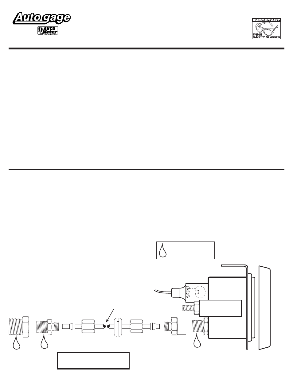
1
⁄
4
” NPT x
1
⁄
8
”
NPT Adapter
(Use if
Necessary)
1
⁄
8
” NPT x
1
⁄
8
”
APT Tube
Connector
Ferrule
Ferrule
Compression
Nut
Compression
Nut
Rubber
Grommet
1
⁄
8
” NPT x
1
⁄
8
”
APT Tube
Connector
U-Bracket
Snap-On
Chrome Bezel
Steel Panel
To 12V Lighting Circuit
Use teflon sealing tape
or sealing compound
on all pipe thread joints
Pressure
Tubing
NOTe: NyLON PReSSURe TUBING
MUST PROTRUDe OUT FeRRULe
eND. (APPROX.
1
⁄
16
” TO
3
⁄
16
”