Voltmeter, Water temperature, Final procedure – Auto Meter 2360 User Manual
Page 2: For service send to: auto meter products, inc
12 MONTH LIMITeD WARRANTY
Auto Meter Products, Inc. warrants to the consumer that all Auto Meter High Performance products will be free from defects in material and workmanship for a period of twelve (12) months from date of the
original purchase. Products that fail within this 12 month warranty period will be repaired or replaced at Auto Meter’s option to the consumer, when it is determined by Auto Meter Products, Inc. that the product
failed due to defects in material or workmanship. This warranty is limited to the repair or replacement of parts in the Auto Meter instruments. In no event shall this warranty exceed the original purchase price of
the Auto Meter instruments nor shall Auto Meter Products, Inc. be responsible for special, incidental or consequential damages or costs incurred due to the failure of this product. Warranty claims to Auto Meter
must be transportation prepaid and accompanied with dated proof of purchase. This warranty applies only to the original purchaser of product and is non-transferable. All implied warranties shall be limited in
duration to the said 12 month warranty period. Breaking the instrument seal, improper use or installation, accident, water damage, abuse, unauthorized repairs or alterations voids this warranty. Auto Meter
Products, Inc. disclaims any liability for consequential damages due to breach of any written or implied warranty on all products manufactured by Auto Meter.
SeRVICe
For service send your product to Auto Meter in a well packed shipping carton. Please include a note explaining what the problem is, the year and model of your vehicle, engine size, etc. and
your phone number. If you are sending product back for Warranty adjustment, you must include a copy (or original) of your sales receipt from the place of purchase.
FOR SeRVICe SeND TO:
AUTO MeTeR PRODUCTS, INC.
413 W. elm St., Sycamore, IL 60178 USA (815) 899-0801
email us at [email protected]
© 2007 Auto Meter Products, Inc. 2650-318X-00 Rev. J 9/12/00
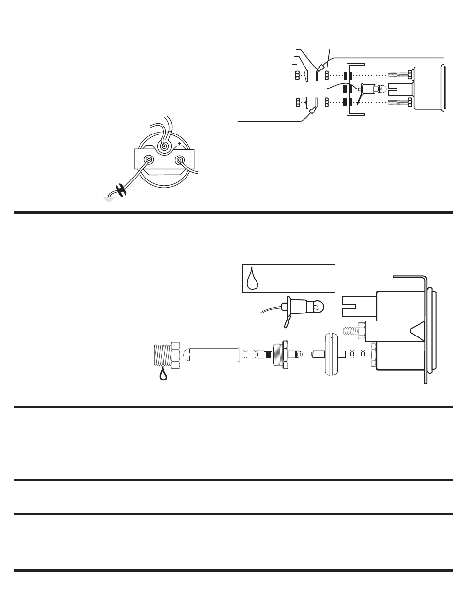
Voltmeter
1. Negative (-) battery cable should remain disconnected.
2. Fasten voltmeter in metal panel using U-bracket and two M5 metric
nuts. Tighten firmly, but do not bend or distort brackets.
3. Cut two lengths of 18-gauge wire. Auto Meter Kit No. 2214 is
recommended. One wire is for connecting gauge to fuse box, the
other connects to good engine ground. Strip insulation back
1
⁄
4
” on
one end of each wire. Attach terminal lug and wire to positive (+)
terminal on back of gauge as shown above. Connect other end of this
wire to appropriate 12V source at fuse box. Attach the ground wire to
negative (-) terminal on back of gauge as shown above and connect
other end to good dash or chassis ground bolt.
See final procedures to complete installation.
Water Temperature
1. Drain antifreeze from
cooled radiator into a container. Never drain
hot coolant! Save antifreeze to refill radiator after installation.
2. Drill a
7
⁄
8
” dia. hole in the firewall and route temperature sensing bulb
through mounted panel first and then through firewall. Install a rubber
grommet provided in firewall hole to hold gauge tubing in place.
3. Locate the original temperature sending unit port (see caution on
front of this instruction) and replace with gauge sending unit using the
1
⁄
2
” NPT adapter supplied. Using sealing compound on threads, insert
and tighten mounting nut in the port in engine. Insert temperature
sensing bulb into mounting nut and carefully thread the sealing nut
into the mounting nut. Be sure to hold the mounting nut securely
while tightening sealing nut. Check the tubing is free from hazard of
moving parts or hot engine components.
4. Refill radiator with coolant.
Final Procedure
1. Insert light bulb and socket assembly into back of gauge. Connect
red lighting wire to 12V power source in dash lighting circuit. Light
socket is grounded through gauge case. It may be necessary to
attach a separate ground wire between the case stud and good
engine ground if light does not operate.
2. Reconnect negative(-) battery cable. Re-program your clock and
radio if necessary.
1/2” NPT
Mounting Nut
Temperature
Sensing Bulb
Grommet
U-Bracket
Steel Panel
To 12V
Lighting Circuit
To Ground
5. Secure gauge in mounted panel using non-insulated mounting
bracket, two lockwashers, and two M5 metric nuts.
See final procedures to complete installation.
Use teflon sealing tape
or sealing compound
on all pipe thread joints
Sealing
Nut
Capillary
Tubing
3. Wrap a clean rag around fittings on back of oil pressure gauge and
place a pan on the floor under them to protect vehicle interior from
potential leaking oil. Start the engine and run for 30 seconds. Shut
off engine and check rag for leaks. If none appear, start engine again
and visually check all connections for leaks.
Volt
Gauge
(top view)
(+)
(-)
To Good Dash or
Chassis Ground
Ignition Switch
Accessory Terminal
or Other 12V
Source
To 12V Lighting Circuit
To 12V Dash Lighting Circuit (Red)
To Ground
Grommet
To Dash or Chassis Ground
U-Bracket
Ignition Switch
Accessory Terminal or
Other Switched Source
NOTe: Whenever removing
temp. sensing bulb, loosen
sealing nut but DO NOT
allow mounting nut to rotate.
Rotation may break capillary
tubing, thus voiding warranty.
To
Ground
Nut (outer)
Terminal Lug
Split Lockwasher
Nut (inner)
Steel Mounting U-Bracket
with Plastic Insulators