Fuel level, Voltmeter, Ammeter – Auto Meter 5747 User Manual
Page 2: Wiring, Warning, Service
FOR SERVICE CONTACT: AUTO METER PRODUCTS Inc. 413 W. Elm St., Sycamore, IL 60178 USA (866)248-6357 or
Email us at [email protected]
© 2012 Auto Meter Products, Inc.
2650-1079-00 Rev. C 09/26/12
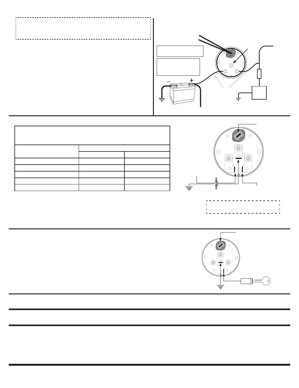
Fuel Level
1. Gauge connects to fuel sender on fuel tank. Existing wires may be used, or route proper length of
18 gage, wire from fuel tank to gauge. If a new hole is drilled in the firewall a grommet is recommended.
Connect one end to terminal post on fuel level sender and the opposite end to the sender (S) terminal
spade on back of gauge.
2. Connect ground wire from ground post on gauge to suitable chassis ground.
3. Connect wire from ignition switch to the positive
I (+) terminal on the back of gauge. See figure right.
4. Reconnect negative (-) battery cable.
5. Be sure that body or mounting flange of sender is grounded to suitable chassis ground.
Voltmeter
1. Using 18 gage wire, route one length through firewall. If a new hole is drilled in the firewall
a grommet is recommended. Attach one end to the negative GND (-) spade terminal on
back of gauge, and the opposite end to a good engine ground. See illustration at right.
2. Attach one length of wire to the positive
I
(+) terminal on back of gauge and opposite end
to 12V terminal on ignition switch or other 12V switched power source.
3. Reconnect negative (-) battery cable.
To 12V Terminal on
Ignition Switch or other
switched 12V source.
Auto Meter warrants to the consumer that this product will be free from defects in materials and workmanship for a period of twelve (12) months from the date of the original purchase. Products that fail
within this 12 month warranty period will be repaired or replaced at the manufacturer’s option to the consumer, when determined by the manufacturer that the product failed because of defects in material
or workmanship. This warranty is limited to the repair or replacement of parts in the instrument and the necessary labor done by the manufacturer to affect the repair or replacement of the instrument. In
no event shall this warranty exceed the original purchase price of the instrument, nor shall the manufacturer be responsible for special, incidental or consequential damages or costs incurred due to failure
of this product. Warranty claims to the manufacturer must be transportation prepaid and accompanied with dated proof of purchase. This warranty applies only to the original purchaser of product and is
non-transferable. All implied warranties shall be limited in duration to the said 12 month warranty period. Breaking the meter seal, improper use or installation, accident, water damage, abuse, unauthorized
repairs or alterations voids this warranty. The manufacturer disclaims any liability for consequential damages due to breach of any written or implied warranty on
all products made by the manufacturer.
12 MONTH LIMITED WARRANTY
Ammeter
1. 10-gage wire or larger must be used.
2.
IMPORTANT: Verify that base nuts on both meter terminals are tight. Tighten base
nuts prior to installing terminal lugs and wires. Connect ammeter as shown.
CAUTION:
DO NOT CONNECT THE AMMETER ACROSS THE BATTERY.
3.
IMPORTANT: Terminal lugs must be BOTH crimped and soldered to wire; star
lockwashers must be used on both sides of terminal lugs.
4. Tighten terminal nuts to compress star lockwashers into terminal lugs.
5. Verify that
none of the ammeter connections are to ground.
6. Reconnect negative (-) battery cable.
7. Leaving engine
off, turn on lights. Indicator should read negative (-). If it reads
positive (+), disconnect neg. battery terminal and reverse the wires on back of meter,
then reconnect neg. battery terminal.
Before starting engine, double check that all
connections are tight. After starting engine, check wiring connections for hot spots.
Be prepared to shut engine off
immediately if hot spots are detected.
Note: Before beginning installation, check to make sure stated resistance range for the gauge
matches your sending unit value for proper operation. The chart below may be helpful in
determining what resistance range of gauge to use. For further assistance please contact
Tech Support at 866-248-6357.
SENDER RESISTANCE (OHMS)
EMPTY
FULL
For most GM vehicles to 1997
0
90
For most Ford and Chrysler vehicles
73
8-12
Use 3262 Fuel level sender
240
33
For most GM vehicles before 1965
0
30
Most ‘89 and newer Fords
16
158
S I
12V Battery
To
Alternator
B(
+
) Alt.
Output
Fuse Box
AMMETER
Vehicle
Accessories
Positive battery/
Starter cable
Engine
Ground
Engine
Ground
Example wiring of a typical Ammeter installation. Consult vehicle Mfr. for
specific wiring details and safety considerations.
WARNING:
Vehicle may contain fusible
links. Do not disable or remove
any fusible links in the course
of installing an ammeter.
Light wires
10 gauge wire
or larger must
be used.
Caution: Do Not over tighten
nuts on back of gauge.
+
-
Wiring
Read
before installing: Must be installed by experienced technician.
WARNING
Have your maximum alternator output tested. Choice of improper ammeter rating
and/or wire size, and any loose connections can cause dangerous overheating,
which could lead to a fire in the vehicle. Ammeter and wire should have a capacity
of at least 10 amps more than your vehicle’s maximum alternator output.
Not
Used
Contact Auto Meter service if help is needed in determining your sender resistance.
If you have questions regarding the operation or installation of your instrument(s), please contact Auto Meter Technical Service at 866-248-6357. You may also email us at
[email protected]. Additional information can also be found at http://www.autometer.com
NOTE: Failure to ground sender as in step 5
may result in inoperable gauge.
SERVICE
For service send your product to Auto Meter in a well packed shipping carton. Please include a note explaining what the problem is along with your phone number. If you are sending product back
for Warranty adjustment, you must include a copy (or original) of your sales receipt from the place of purchase.
GND
S I
Twist-In Light
Ground
Twist-In Light
GAUGE
(back view)
GND
S I
Connect to terminal post
on sender on fuel tank.
To ignition switch
Ground
Grommet
- 5815 2092 2093 880430 880260 880243 880241 880431 880429 880428 880242 880240 880016 880030 3837 3849 3827 3815 3892 3848 3816 3813 8049 8037 8016 8014 8092 8048 8027 8015 3613-00406 3649-00406 3627-00406 3692-00406 5837-00407 5891-00407 5827-00407 5837-00406 5891-00406 5827-00406 5937-M 5937 5949 5948 5927 5915 5992 5948-M 5927-M 5916 5913 7115 7148 7127 7116 7113 7149 7137 4837 4791 4737 4891 4757 4848 4727 4815 4814 4716 4748 4827 4816 4715 4714 6192 6127 6148 6115 7914 6137 6113 7915 7916 7927 7937 6148-M 6137-M 7991 6127-M 1294