Wiring sensor wiring, Powering the dcr-1006a, Automation products group, inc – APG DCR-1006A user manual User Manual
Page 9: Red pin 1 (brown), Black pin 3 (blue), Dst sensor, Mnu sensor
Rev. A1, 2/14
DCR-1006A Ultrasonic Controller
9
Automation Products Group, Inc.
APG...Providing tailored solutions for measurement applications
Tel: 1/888/525-7300 • Fax: 1/435/753-7490 • www.apgsensors.com • [email protected]
• Wiring
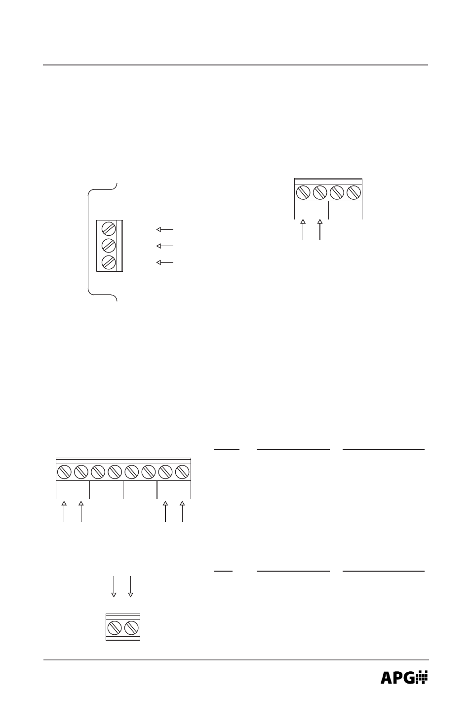
Sensor Wiring
The DCR-1006A is compatible with DST and MNU series ultrasonic sensors.
MNU Standard Cable Micro-Connector
24V
Red
Pin 1 (Brown)
GND
Black
Pin 3 (Blue)
A
White
Pin 2 (White)
B
Green
Pin 4 (Black)
DST
Standard Cable Micro-Connector
+
Red
Pin 1 (Brown)
-
Black
Pin 3 (Blue)
Powering the DCR-1006A
Power to the DCR-1006A can be supplied from either 85-264 VAC or 12-28 VDC.
NOTE: terminals will source 24 VDC
when powering via AC voltage.
OR
GND
Ground
Neutral
Hot
85-264 VAC
INPUT
AC/N (-)
AC/L (+)
Powering with AC Voltage
24V
GN
D
Vs
OUT
DC Voltage Powered
12-24 VDC
INPUT
DST Sensor
DST
+
_
24V
GN
D
Vs
A (-)
B(+)
A1 (-)
B1(+)
OUT
MNU Sensor
- LPU-2127 user manual (27 pages)
- LPU-2428 user manual (36 pages)
- MNU Modbus Sensor user manual (40 pages)
- LOE Tank Cloud Master Sensor user manual (36 pages)
- IRU-2000 datasheet (4 pages)
- IRU-3000 datasheet (4 pages)
- IRU-2000 user manual (42 pages)
- IRU-2420 datasheet (4 pages)
- IRU-3430 datasheet (4 pages)
- IRU-5000 datasheet (4 pages)
- IRU-6429 datasheet (4 pages)
- IRU-9400 datasheet (4 pages)
- IRU-3000 user manual (28 pages)
- DST Sensors datasheet (4 pages)
- PT-L1-C datasheet (4 pages)
- PT-L1-C user manual (8 pages)
- PT-L3-C user manual (8 pages)
- PT-L10-C user manual (8 pages)
- PT-L9 datasheet (4 pages)
- PT-L9 user manual (8 pages)
- PT-400 datasheet (4 pages)
- PT-400 user manual (17 pages)
- Hammer Union Pressure Tansmitter datasheet (4 pages)
- Hammer Union Pressure Tansmitter user manual (13 pages)
- PG5 datasheet (4 pages)
- PG5 user manual (28 pages)
- PG7 datasheet (4 pages)
- PG7 user manual (31 pages)
- PG10 datasheet (4 pages)
- PG10 user manual (42 pages)
- PT-500 datasheet (4 pages)
- PT-500 user manual (16 pages)
- PT-500 Modbus user manual (32 pages)
- PT-503 datasheet (3 pages)
- KA Cable Suspended datasheet (6 pages)
- KA Cable Suspended user manual (18 pages)
- FT-100 Cable Suspended datasheet (4 pages)
- FT-100 Cable Suspended user manual (8 pages)
- FL Series datasheet (4 pages)
- FLE Series user manual (12 pages)
- FLR Series user manual (28 pages)
- FLX datasheet (4 pages)
- FLX user manual (16 pages)
- LF Series datasheet (10 pages)
- LFE Series user manual (8 pages)