Wiring the pg10, Battery replacement, 8_pin connector wiring – APG PG10 user manual User Manual
Page 37
Rev. B, 6/11
PG10
37
Automation Products Group, Inc.
APG...Providing tailored solutions for measurement applications
Tel: 1/888/525-7300 • Fax: 1/435/753-7490 • www.apgsensors.com • [email protected]
Wiring the PG10
Battery Replacement:
Step 1: Untwist the display locking ring (on the face of the gauge) counter-
clockwise until the ring releases the display from the gauge.
Step 2: Remove the front display to access the batteries.
Step 3: Replace the front display ensuring proper alignment and secure into
place using the locking ring.
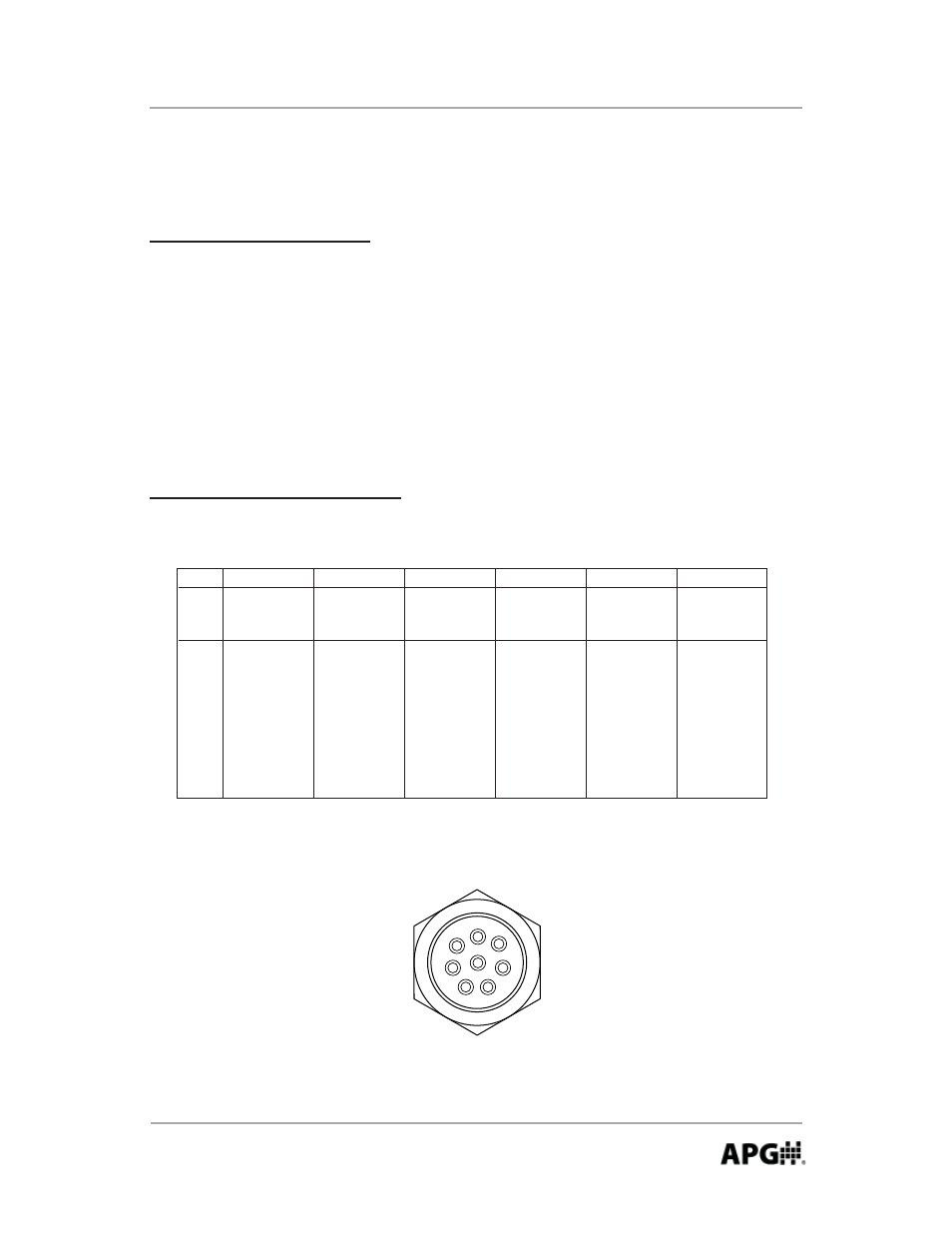
3
5
2
8
6
4
7
1
8_Pin Connector Wiring:
PG10 Pin Out Table
L1
L2
L4-C2
4-20 mA
0-2 VDC
with Battery
Power
Power
2 SS Relays
with External
Power
8 Pin Connector
1
+ Excitation
n/a
+ Excitation
2
- Excitation
+ Output
- Excitation
3
n/a
- Output
4
n/a
n/a
5
n/a
n/a
6
7
8
n/a
n/a
L4-C4
2 SPDT Relays
with External
Power
+ Excitation
- Excitation
Relay 1 Com*
Relay 1 NC*
Relay 1 NO*
Relay 2 Com*
L5
RS-485
with External
Power
+ Excitation
- Excitation
SS Relay 1*
SS Relay 1*
SS Relay 2*
SS Relay 2*
*Optional (C2 or C4) relay outputs
n/a indicates not applicable.
L3
0-5 VDC
with External
+ Excitation
+ Output
- Excitation
n/a
n/a
n/a
n/a
Relay 2 NC*
Relay 2 NO*
RS-485 (A)
RS-485 (B)
SS Relay 1*
SS Relay 1*
SS Relay 2*
SS Relay 2*
n/a
n/a
SS Relay 1*
SS Relay 1*
SS Relay 2*
SS Relay 2*
- Output