Step 1 - parts layout, Step 2 - beam arch as- sembly – Anchor NAVI-TRAC LITE PAVILLION - 12 TO 24 User Manual
Page 7
7
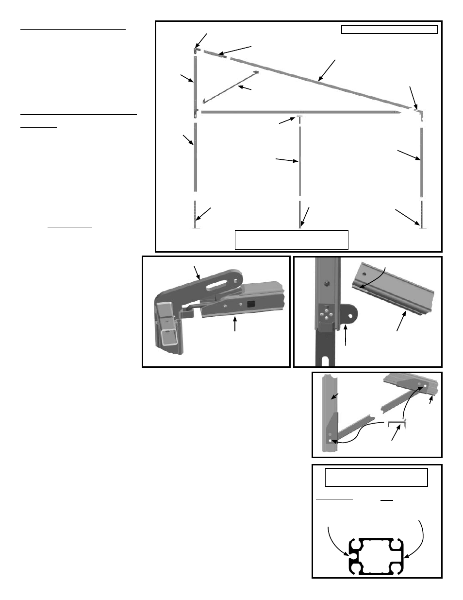
Step 1 - Parts Layout
Follow the directions on the previ-
ous page for squaring and marking
for the frame.
Lay out the parts neatly in their ap-
proximate location, as if the frame
were collapsed onto the ground.
(Figure 1a)
Step 2 - Beam Arch As-
sembly
Assemble the fi rst beam arch in the
following order:
Assemble upper triangle fi rst
by fastening upright rear upper
splice to ridge weldment using
one of the pins attached to the
ridge weldment.
Drop hook end of Eave Projec-
tion into Eave End Weldment
Bracket. (Figure 2a) Note: On
24’ projection, Eave projection
is spliced. Slide Eave Splice
Projection into 24’ Eave Projec-
tion and fasten using 1/2” bolt
and nut.
Drop slotted end of Eave
Projection down over ear
located at bottom of upright
rear upper splice and pin
using a tension lock pin.
(Figure 2b)
Assemble Rafter Splice
Projection to Rafter using
1/2” bolt and nut provided
(required only on frames
over 20’ projection)
Slide Rafter up onto ridge
weldment and affi x using method detailed as follows:
On rafters with “X” cables in one of the adjacent bays such as end
bays (see illustration on page 5) connection must be made using the
eye nuts and bolts shipped with the “X” cables. Eye nut must face in
the direction of the “X” cabled bay because it is used for connection of
the “X” cables. (See Step 3)
In the case where there are two “X” cabled bay adjacent to one
another, the connection must be made using an eye bolt with eye nut.
(not usual)
On rafters with no “X” cables attach the rafter using the pin attached to
the ridge weldment.
6. On frames with 20’ projection or more, rafter brace is now attached to triangle.
Rafter Brace will only fi t one way- so if you are having trouble with alignment,
turn the brace around so that the opposite ends are now at the rafter and up-
right rear upper splice. (See Figure 2c)
7. Assemble uprights by sliding adjustable base plates into uprights and bolting
with bolts provided. See Figure 2d for assistance in assembling the upright in
the correct position.
8. On Rear upright, slide Upright rear upper splice down into bottom upright and
pin with a tension lock pin. See Figure 2d for assistance in assembling the
upright in the correct position.
9. Assemble all Beam arches with baseplates in correct position for raising.
•
•
•
•
1.
2.
3.
4.
5.
•
•
•
Eave End Weldment
Eave projection
Figure 2a
Eave projection
Slot
Upright Rear Upper
Splice Ear
Figure 2b
Figure 2c
Upright Rear
Upper Splice
Rafter
Tension
Lock Pin
Rafter Brace
Flat side of
upright. toward
outside of frame.
Channeled
side of upright.
toward inside
of frame.
Cross-sectional view of
Navi-Trac Lite Beam
Figure 2d
Ridge
Weldment
Rafter Brace (only
on frames 20’ pro-
jection and larger.
Rafter
Upright
Rear
Upper
Splice
Upright
Upright (only on
frames over 20’
projection.)
Upright
Eave End
Weldment
Eave Projection
End Upright
Eave Weld-
ment
Base Plate
Adjustable
2-Hole
Base Plate
Adjustable
4-Hole
Base Plate
Adjustable
4-Hole
Rafter Splice
Projection
Figure 1
Note: End Upright used only on
frames larger that 20’ projection.
22’ Projection Frame Shown