Step 4 - joining beam arches – Anchor NAVI-TRAC LITE PAVILLION - 12 TO 24 User Manual
Page 10
10
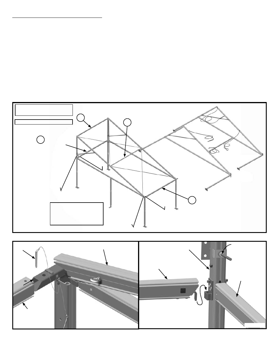
Front Eave
Rafter
Figure 4b
Longer
Pin
Upright Rear
Upper Splice
Gable End Mid
Eave
Eave Projection
Figure 4c
Frame attaching
bracket.
Step 4 - Joining Beam Arches
Join in the order listed: (Figure 4a)
Front Eave - slide one end of front eave tube onto end eave weldment with bottom channel down. Align holes and pin
with one of the pins attached to the weldment. Figure 4b.
Gable End Mid Eave - drop gable end mid eave into brackets on upright rear upper splices. Figure 4c
Ridge - fi t ridge into slots provided in ridge weldment. Figure 4d.
Purlin - Drop curved end of purlin into rafter bracket. See fi gures 4e and 4f. Drop square hook end into the correspond-
ing rafter bracket.
Note: If optional installation kit has been used, remove eyenut at lower end of fi rst rafter and replace with nut
before snapping cables in place.
Note: If Installation Kit has been purchased, the short lifting bar may be used to lift bars into place.
Snap lower ends of cables onto their respective eye nuts. Square up frame by tightening turnbuckles
•
•
•
•
•
•
Figure 4a
Front Eave
Ridge
22’ Projection Frame Shown
Gable End
Mid Eave
Purlin
Frame sizes under 16’
projection have only (2)
cables per bay and no
purlins.
Parts labeled numerically in
the order to be installed.
1
2
4
3