Brake lathes, Caution – AMMCO 7000 Disc Rotor Lathe User Manual
Page 10
Arbor Installation
The 1" arbor shipped with the lathe has been carefully matched
to the lathe during final assembly and testing. Witness marks
have been etched onto the arbor and spindle for repeatable, pre-
cise alignment.
The witness marks should be carefully aligned when installing
the arbor, Fig. B 1. A true running arbor is essential to profes-
sional quality rotor reconditioning.
The drawbar, which can be tightened or loosened at the rear of
the spindle, pulls the hardened and ground tapers of the arbor
into the matching seats.
Adapters
Although the adapters, arbor, and spindle are made
of top grade steel and are turned, hardened, and pre-
cision ground to close tolerances, great care should
be taken in their use, handling, and storage. Even
the smallest nick, scratch or loose chip on the mat-
ing machined surfaces, Fig. B 2, can cause incorrect
rotor mounting alignment.This will cause inaccurate
machining.
Note: A light film of oil should be put on all adapters to protect
the machined surfaces from rust. Always inspect the surface,
the face and the seating tapers of each part. Wipe each part
clean before and after using it. Carefully correct any flaw with a
fine stone. If damage cannot be corrected, replace the part.
Basic Operation
To completely understand rotor turning you must have a
knowledge of the lathe itself.
The spindle is a motor driven shaft that turns the arbor on
which the brake rotor is mounted. By turning the rotor and hold-
ing a cutting tool to the rotor, metal can be removed.
By operating the cross feed lever the cutting tool is automati-
cally drawn across the rotor brake face as the cross feed moves
away from the tool while the rotor turns. Cross feed may also
be done manually using the cross feed handwheel.
Do not try to move any feed levers or dials without
the drive motor running. Damage may occur to the
gear trains.
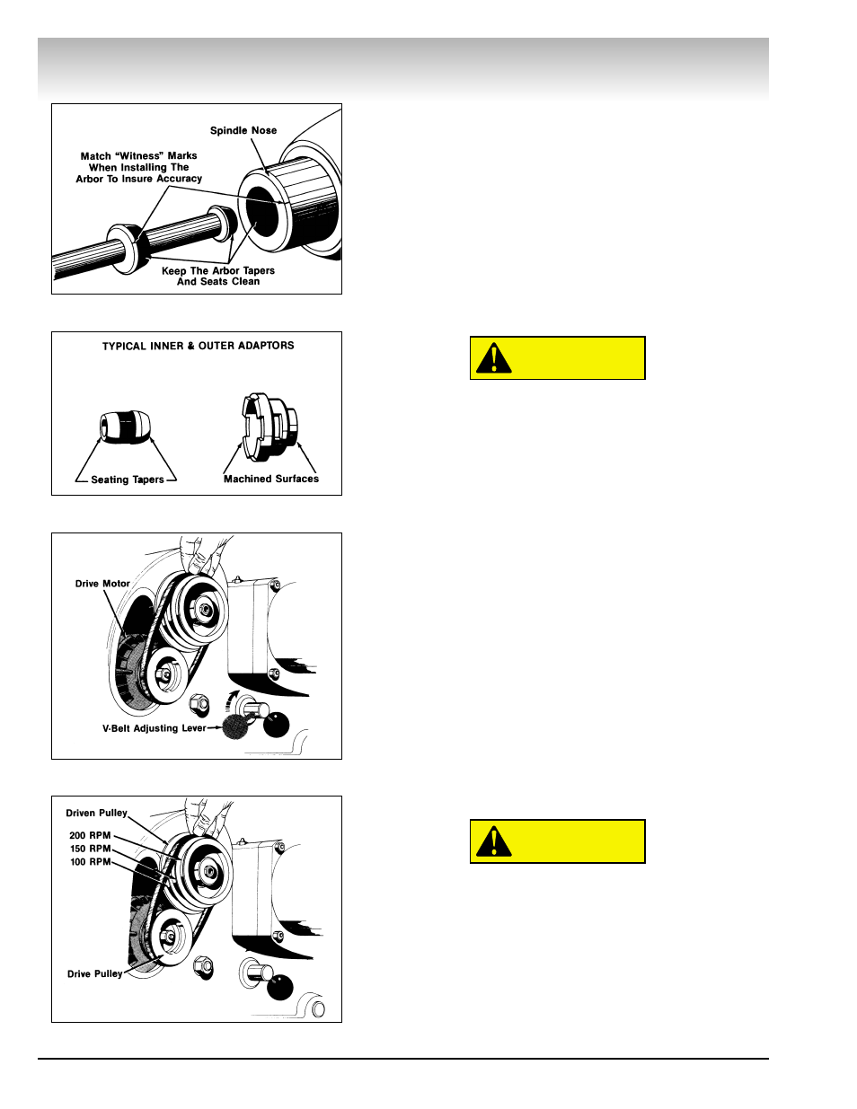
Adjustments
Spindle Speed - Release the belt tension by moving the V-belt
adjusting lever clockwise, Fig. B 3. Move the belt to the pulley
groove that will give the correct spindle speed for the cut to be
taken, Fig. B 4.
CAUTION
CAUTION
Brake Lathes
4 • AMMCO 7000 Brake Lathes
Figure B1
Figure B2
Figure B3
Figure B4