JLG 40RTS ANSI Service Manual User Manual
Page 29
SECTION 2 - PROCEDURES
3120691
– JLG Sizzor –
2-13
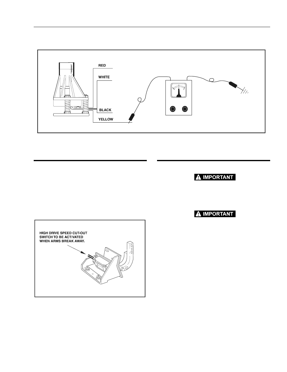
2.13 LIMIT SWITCH ADJUSTMENT
PROCEDURE
NOTE: The high drive limit switch is located on top of the
frame at the front of the machine.
1.
With the machine in the stowed position raise the
platform until the arms break away from each other.
2.
The high drive speed switch should be set to cut out
high drive at this point
2.14 DRIVE PUMP START-UP PROCEDURE
THE FOLLOWING PROCEDURE SHOULD ALWAYS BE PER-
FORMED WHEN STARTING A NEW PUMP OR WHEN RESTARTING
AN INSTALLATION IN WHICH EITHER THE PUMP OR MOTOR
HAVE BEEN REMOVED FROM THE SYSTEM.
THE FOLLOWING PROCEDURE SHOULD ALWAYS BE PER-
FORMED WHEN STARTING A NEW PUMP OR WHEN RESTARTING
AN INSTALLATION IN WHICH EITHER THE PUMP OR MOTOR
HAVE BEEN REMOVED FROM THE SYSTEM.
THE FOLLOWING PROCEDURE MAY REQUIRE THE MACHINE TO
BE DISABLED (WHEELS RAISED OFF THE GROUND, DRIVE
FUNCTION DISCONNECTED, ETC.) WHILE PERFORMING THE
PROCEDURE IN ORDER TO PREVENT INJURY TO TECHNICIAN
AND OTHER PERSONNEL. TAKE NECESSARY SAFETY PRECAU-
TIONS BEFORE MOVING THE MACHINE.
Prior to installing pump and/or motor, inspect unit(s) for
damage incurred during shipping and handling. Make
certain all system components (reservoir, hoses, valves,
fittings, heat exchanger, etc.) are clean prior to filling with
hydraulic fluid.
Fill reservoir with recommended hydraulic fluid, which
should be passed through a 10 micron (nominal, no
bypass) filter prior to entering the reservoir. The use of
contaminated fluid will cause damage to components,
which may result in unexpected machine movement.
Figure 2-16. Tilt Alarm Switch - Voltmeter Adjustment
Figure 2-17. Limit Switch Cut-Out