Integral brake check, Integral brake check -11 – JLG 660AJ Service Manual User Manual
Page 55
SECTION 3 - CHASSIS & TURNTABLE
3121616
– JLG Lift –
3-11
9.
Place Input Carrier Sub-Assembly (3A) on Output Sun
Gear (11) splines. Drop Input Sun (10) in mesh with
planet gears for specific ratios, if required. (No timing
required).
10.
Grease O-Ring (17) and insert in groove in Cover Sub-
Assembly (6).
11.
Install Cover Sub-Assembly (6) in Ring Gear (1E) counter-
bore and install Retaining Ring (6G) in groove in Ring
Gear (1E).
12.
Attach ID Tag (15) on unit using Drive Screws (16).
13.
Check disconnect, roll and air check unit, leak check
brake, and record release pressure.
14.
Insert Plastic Plug (12) if applicable.
Integral Brake Check
1.
Using appropriate fittings, connect hydraulic line from
hand pump to brake port.
2.
Check brake is set by trying to rotate Input Shaft (9). This
can be accomplished by installing an appropriate tool
(any tool that can locate on splines of Input Coupling (7),
such as a mating splined shaft) into Input Coupling (7).
3.
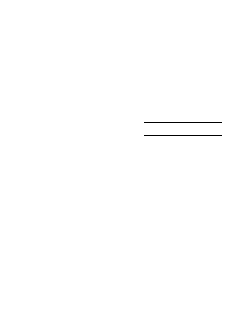
Bleed brake. Increase hydraulic pressure gradually while
trying to rotate input until brake just starts to release.
Note this pressure. Make sure pressure falls into appro-
priate range below.
4.
Increase pressure to 1,000 psi and hold for 30 seconds to
check for leaks. Repair leaks if necessary.
NOTE: Make sure brake re-engages when pressure is released.
NOTE: When done, make sure Input Coupling (7) is centered in
Spindle (1A) to make installation of motor possible without
release of brake.
BRAKE
CODE
JUST RELEASE
PRESSURE RANGE
PSI
BAR
A
200-260
13.7-17.9
B
170-220
11.7-15.1
C
140-185
9.6-12.7
D
130-155
8.9-10.6
E
115-145
7.9-9.9