Platform control cover, Drive motion alarm, Driving and work lights – Snorkel AB80J User Manual
Page 41: Platform glazier package
Chapter 7 – Prestart Inspection
AB80J/AB85J – 0420453
37
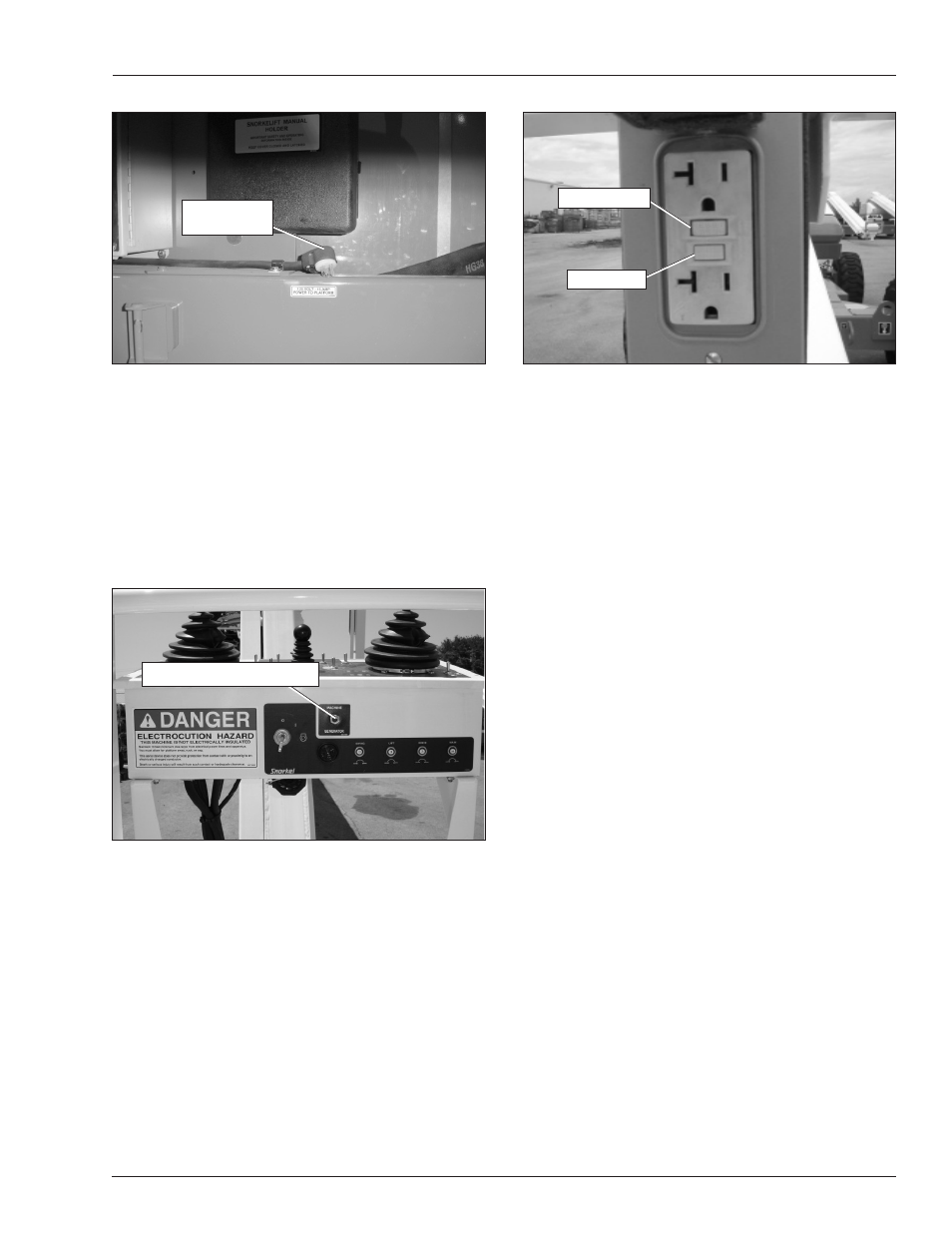
Figure 7.22 – Electrical Power Outlet
2. Plug an electrical tool into the outlet and verify the
power is off.
• If the power was off, push the reset button to
restore power.
• If the power was on, repair or replace the recep-
tacle.
Platform Control Cover
The machine may be equipped with an optional platform
control cover. Inspect the cover to ensure it fits properly
over the control panel.
Drive Motion Alarm
The machine may be equipped with an optional drive
motion alarm. Drive in both the forward and reverse direc-
tions to ensure that the alarm sounds to warn personnel
in the area that the aerial platform is in motion.
Driving and Work Lights
The machine may be equipped with driving lights and/or
platform work lights. Turn the engine on and use the
switch on the back of each light to momentarily turn it on
to see that it works.
Platform Glazier Package
Inspect the glazier trays (refer to Figure 7.23) and keeper
pins to make sure they are in good condition and are not
bent or distorted. The straps and padding must be in good
condition and not worn, cut or frayed.
Figure 7.20 – Power-Input Connector
Some machines may have an electrical cable already
plugged into the power-input connector. In that case,
power is supplied by an optional AC generator. An ex-
ternal power source is not required.
With the engine running, place the machine/generator
control (refer to Figure 7.21) in the generator position to
provide electrical power to the two electrical outlets at
the platform and to the outlet on the end of the genera-
tor housing.
Figure 7.21 – Upper Control Panel Front
Plug an electrical tool into the receptacle at the platform
and at the generator and try to operate the tool to verify
proper operation of the outlet.
The outlet is equipped with a ground fault circuit inter-
rupter (GFCI). Use the following procedure to test the
GFCI.
1. Push the test button (refer to Figure 7.22).
Power-Input
Connector
Machine/Generator Switch
Test Button
Reset Button