Introduction, Pre-operation and safety inspection, Diesel model inspection – Snorkel SL30N-sn9600-11199CE User Manual
Page 3: Electric model inspection, System function inspection
3
Introduction
This manual covers SL26/30 Narrow Work Plat-
forms. This manual must be stored on the
machine at all times.
Pre-Operation and Safety
Inspection
Read, understand and follow all safety rules
and operating instructions and then perform
the following steps each day before use.
1. Remove module covers and inspect for dam-
age, oil leaks or missing parts.
2. Check the level of the hydraulic oil with the
platform fully lowered. Oil should be visible in
the sight gauge. Add hydraulic oil, if necessary
(see Specifications, back cover).
3. Check that the fluid level in the batteries is
correct (see Battery Maintenance, page 6).
4. Carefully inspect the entire work platform for
damage such as cracked welds or structural
members, loose or missing parts, oil leaks,
damaged cables or hoses, loose connections
and tire damage.
5. Check that all guardrails are securely in place
with all fasteners properly torqued.
6. Place the Chassis Emergency Stop Switch to
the ON position by pulling the button out.
Diesel Model inspection
1. Check fuel supply.
2. Check engine oil level with dipstick.
3. While the engine is cool check the radiator
coolant level. DO NOT check coolant when the
engine or radiator is hot.
Electric Model inspection
1. Verify batteries are charged (see Battery
Maintenance, page 6).
2. Check that AC extension cord has been discon-
nected from charger.
System Function Inspection
STAND CLEAR of the work platform while
performing the following checks.
Before operating the work platform survey
the work area for surface hazards such as
holes, drop-offs, bumps and debris.
Check in ALL directions, including above
the work platform, for obstructions and
electrical conductors.
Protect control console cable from possible
damage while performing checks.
1. Unhook Controller from front guardrail. Firmly
grasp Controller hanger in such a manner that
the Interlock Lever can be depressed, while
performing the following checks from the
ground.
2. Pull Controller Emergency Stop Button out to
ON position.
3. Turn Controller Key Switch clockwise to ON.
Turn fully clockwise to start engine (Diesel
Model only).
Note: On Diesel Models, if the engine is cold,
turn the key fully counterclockwise and hold for
6 seconds to engage the glow plugs.
4. Turn Drive/Lift Switch to DRIVE position.
5. With the Speed Range Switch first in HIGH
TORQUE and then in HIGH SPEED actuate the
Interlock Lever and slowly push the Control
Lever to FORWARD then REVERSE positions
to check for speed and directional control. The
farther you push or pull the Control Lever from
centre the faster the machine will travel.
6. Push Steering Switch RIGHT then LEFT to
check for steering control.
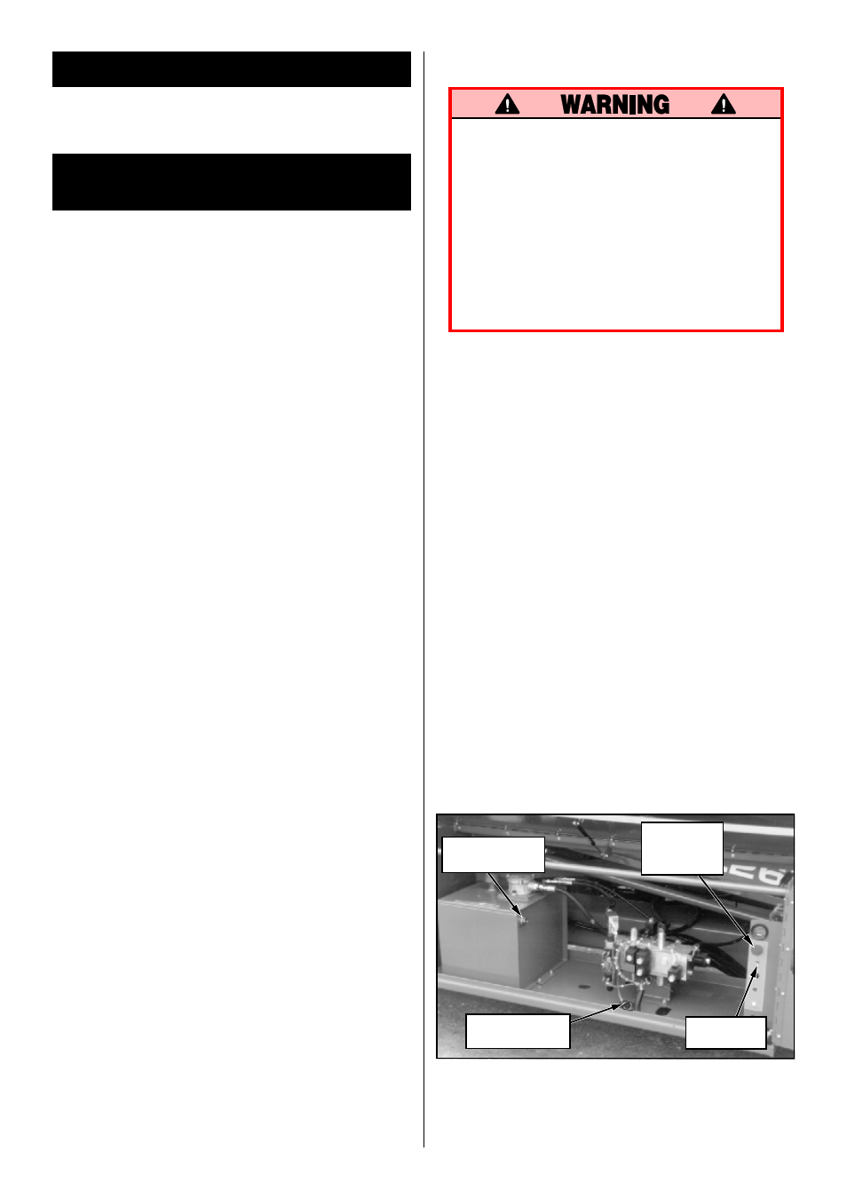
Figure 1: Control Module, Chassis Left Side
Hydraulic Tank
Sight Gauge
Chassis
Emergency
Stop Switch
Emergency
Lowering Valve
Chassis Lift
Switch