Lan für, Nspektion und, Artung – Snorkel MX19-sn18100-19999 User Manual
Page 9: Ontrollliste zur täglichen vorbeugenden, Ystem, Unction, Nspection
Seite 50
Betriebsanleitung
060570-027 MX 15/19
Plan für Inspektion und Wartung
P
LAN FÜR
I
NSPEKTION UND
W
ARTUNG
Zur vollständigen Durchsicht gehören regelmäßige visuelle und Funktionsprüfungen, sowie regelmäßige
kleinere Einstellungen, mit denen eine ordnungsgemäße Funktion gesichert wird. Eine tägliche Prüfung
vermeidet anormalen Verschleiß und verlängert die Lebensdauer aller Systeme. Inspektion und Wartung
müssen in den genannten Zeitabständen durchgeführt werden. Inspektion und Wartung dürfen nur von
Personen vorgenommen werden, die mit den elektrischen und mechanischen Vorgängen der Maschine
vertraut sind.
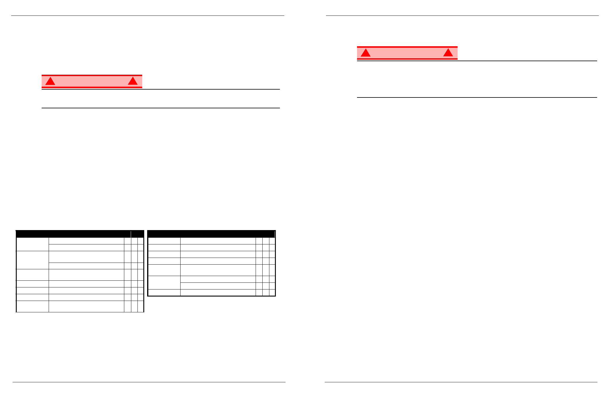
W A R N U N G
!
!
Machen Sie sich vor Durchführung der vorbeugenden Wartung mit der Bedienung der Maschine vertraut.
Das Hubgestell immer blockieren, wenn Wartungsarbeiten bei ausgefahrener Arbeitsbühne durchgeführt
werden müssen.
Die Kontrollliste zur täglichen vorbeugenden Wartung gilt für Wartungsarbeiten der Maschine. Kontrollliste zur
täglichen vorbeugenden Wartung kopieren und zur Kontrolle der Maschine verwenden.
K
ONTROLLLISTE ZUR TÄGLICHEN VORBEUGENDEN
W
ARTUNG
W
ARTUNGSLEGENDE
J = Ja/Akzeptabel
N = Nein/Nicht akzeptabel
R = Repariert/Akzeptabel
V
ORBEUGENDES
W
ARTUNGSPROTOKOLL
Datum: _______________________________________
Eigentümer: ___________________________________
Modell-Nr.:_____________________________________
Serien-Nr.:_____________________________________
Gewartet von: __________________________________
BESCHREIBUNG
INSPEKTION ODER WARTUNG
J
N
R
Batterie
Flüssigkeitsstand prüfen
Batteriekabelzustand prüfen
Fahrwerk
Schläuche auf Klemmstellen oder auf
Scheuerstellen prüfen
Schweißstellen auf Risse prüfen
Steuerkabel
Das Kabel auf äußerlichen Verschleiß, Bandage
oder Quetschstellen kontrollieren
Steuerpult
Schalterfunktion prüfen
Antriebsmotor
Auf Funktion und Lecks prüfen
Hubgestell
Gestell auf Risse prüfen
Notabsenkung
Notsenkventil betätigen undauf Brauchbarkeit
prüfen
Gesamteinheit
Kollisionsschäden prüfen und reparieren
Hydraulikflüssigkeit Flüssigkeitsstand kontrollieren
Hydraulikpumpe
Schlauchverbindungen auf Lecks prüfen
Hydrauliksystem
Auf Lecks prüfen
Schilder
Schilder auf Abblättern, Fehlen oder Lesbarkeit
prüfen und ersetzen
Arbeitsbühnendeck
und Geländer
Schweißstellen auf Risse prüfen
Deckzustand prüfen
Reifen
Auf Schäden prüfen
BESCHREIBUNG
INSPEKTION ODER WARTUNG
J
N
R
System Function Inspection
060570-027 MX 15/19
Operation Manual
Page 7
S
YSTEM
F
UNCTION
I
NSPECTION
Refer to Figure 2 for the locations of various controls and indicators.
W A R N I N G
!
!
STAND CLEAR of the work platform while performing the following checks.
Before operating the work platform, survey the work area for surface hazards such as holes, drop-offs,
bumps and debris.
Check in ALL directions, including above the work platform, for obstructions and electrical conductors.
Protect the control console cable from possible damage while performing checks.
1. Move the machine, if necessary, to an unobstructed area to allow for full elevation.
2. Pull Chassis Emergency Stop Switch to the ON position.
3. Pull Platform Emergency Stop Switch to the ON position.
4. Turn and hold the Chassis Key Switch to CHASSIS. Push the Chassis Lift/Lower Switch to the UP posi-
tion and raise the platform approximately 2,1 m (7 feet). BLOCK THE ELEVATING ASSEMBLY AS
DESCRIBED ON page 12.
5. Visually inspect the elevating assembly, lift cylinder, cables, and hoses for cracked welds and structural
damage, loose hardware, hydraulic leaks, loose wire connections, and erratic operation. Check for miss-
ing or loose parts.
6. Verify that the Depression Mechanism Supports have rotated into position under the machine. REMOVE
THE SCISSOR BRACE AS DESCRIBED ON page 12.
7. Turn and hold the Chassis Key Switch to CHASSIS. Push the Chassis Lift/Lower Switch to the UP posi-
tion and fully elevate the platform. Partially lower the platform by pushing Chassis Lift/Lower Switch to
LOWER, and check for proper operation of the audible lowering alarm.
8. Open the Emergency Lowering Valve (see Figure 3) by pulling the knob out to check for proper opera-
tion. When the platform is lowered, release the knob.
9. Push the Chassis Emergency Stop Switch to check for proper operation. All machine functions should
be disabled. Pull out the Chassis Emergency Stop Switch to resume.
10. Turn the Chassis Key Switch to DECK.
11. Check that route is clear of obstacles (persons, obstructions, holes, and drop-offs, bumps and debris), is
level, and is capable of supporting the wheel loads.
12. Mount the platform and properly close the entrance.
13. Turn the Drive/Lift Switch to DRIVE. While engaging the Interlock Switch, move the Control Handle to
FORWARD, then REVERSE, to check for speed control.
14. Push the Steering Switch RIGHT, then LEFT, to check for steering control.
15. Turn the Drive/Lift Switch to LIFT. Grasp the Control Handle, engaging the Interlock Switch, and push it
forward to check platform lift controls. Raise the platform to full elevation.
16. Pull back on the Control Handle. The platform should descend and the audible lowering alarm should
sound.
17. Push the Platform Emergency Stop Switch to check for proper operation. All machine functions should
be disabled. Pull out the Platform Emergency Stop Switch to resume.