Т³гж 6, Step 4 - mount the connector for remote, Step 5 - install the wiring – Smittybilt 97203 XRC 3.0 3,0001b Winch User Manual
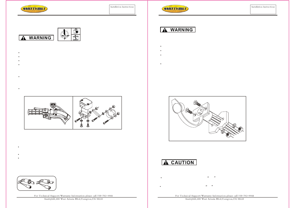
Page 6: Step 3- mount the handlebar switch
TO PREVENT SERIOUS INJURY OR DEATH FROM
ELECTRICAL FIRE:
Do NOT route electrical cables across sharp edges.
Do NOT route electrical cables through or near moving parts.
Do NOT route electrical cables through or near any high heat parts.
Avoid pinch and wear/abrasion points when installing all electrical cables.
TO AVOID INJURY AND PROPERTY DAMAGE:
Use caution when moving or repositioning any vehicle controls so as to not com
promise the safe operation of the ATV. Select a mounting position that will provide
clearance for all vehicle controls.
Before securing the switch cable with tie wraps, make sure that the handlebars
have full range of motion.
Figure 6: handlebar mount. Figure 7: Mini-rocker switch
assembly Exact positioning may vary
depending on ATV make and model.
It is recommended that the switch be installed on the left handlebar. A piece of electrical
tape around the handlebar will help prevent rotation of mount on the handle bar.
Do NOT tighten over any hoses or cables.
Once the handle bar switch is mounted, route the two bullet terminal wires back to
where the contactor will be mounted. Splice the end of the red wire to a key controlled
accessory circuit of the ATV (use the provided wire splice). Using a test light, locate a
suitable wire from the ATV key switch. The wire should only have power when the key
is in the "ON" position.
Figure 8: Use a test light to locate a suitable wire
Step 4 - Mount the Connector for Remote
TO PREVENT SERIOUS INJURY OR DEATH FROM
EXPLOSION:
Do NOT drill into gas tank.
Verify the area is clear behind the mounting location before drilling.
After determining the mounting location for the remote socket, drill three holes and
install. (see figure 9)
Once the remote socket is mounted, route the two bullet terminal wires back to
where the contactor will be mounted. Splice the end of the red wire to a key controlled
accessory circuit of the ATV (use the provided wire splice). Using a test light, locate a
suitable wire from the ATV key switch. The wire should only have power when the key
is in the "ON" position.
NOTE: If installing both switches, both red wires MUST be spliced to a key
controlled accessory circuit of the ATV as described above.
Step 5 - Install the Wiring
Place the supplied terminal boots on wires before securing to the contactor. All wires
must be attached to the contactor before mounting the contactor to the ATV.
Connect one terminal (marked
M+
) of contactor to terminal positive (+) of the
motor with red cable.
Connect one terminal (marked
M-
) of contactor to terminal negative (-) of the
motor with black cable.
Figure 9. Remote socket installation.
-11-
-12-
Step 3- Mount the Handlebar Switch
XRC 3.0 3,0001b Winch
Part # 97203
WWW.SMITTYBILT.COM
XRC 3.0 3,0001b Winch
Part # 97203
WWW.SMITTYBILT.COM