Find the step-by-step diagram for your system, W y rh rc g, W y r g – 2GIG CT100 User Manual
Page 5: W r g, Wn yn r g, O aux, O y r g
4
PG
5
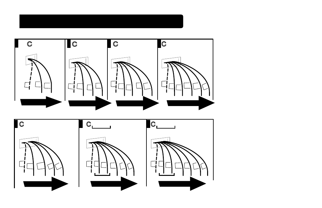
Find the step-by-step diagram for your system
• Select the reference page
with your wiring diagram and
set-up information below.
• The C-wire is optional but
preferred for all installations.
It will make batteries last a
long time. (This connection
is shown as dotted in
diagrams).
• Hot Water systems
accessories are on Page 16.
• If your combination of
wires is not shown, you can
use the wiring table at the
end of the install section
to ind your connections. If
additional help is required,
please contact customer
service.
G
W Y RH RC G
5 Wire
Heat/Cool
From
HVAC
RC
C
Y RH
W
W Y R G
4 Wire
Heat/Cool
From
HVAC
G
C
Y
R
W
W R G
3 Wire
Heat
From
HVAC
C
R
G
W
From
HVAC
C
W
W R
R
2 Wire
Heat
W
IR
ES
W
IR
E
S
W
IR
E
S
W
IR
ES
G
R
Wn Yn R G
Multi-stage Cool
Multi-Stage Heat
From
HVAC
Y
n
C
W
n
B
or
O AUX
n
Y
n
R G
Multi-stage
Heat Pump
w/
Multi-stage
Aux Heat
From
HVAC
R
C
O
or
Wn
B
G
Yn
G
B
or
O Y R G
4 Wire Heat Pump
w/o Aux Heat
From
HVAC
R
C
O
or
Y
B
W
IR
E
S
W
IR
ES
W
IR
E
S
Go To Page 15
Go To Page 16
Go To Page 15
Go To Page 13
Go To Page 14
Go To Page 14
Go To Page 13