2GIG DW20R-345 Recessed DW Contact User Manual
Recessed door contact, Install instructions, Box contents
INSTALL INSTRUCTIONS
The 2GIG‐DW20R‐345 is the industry’s most flexible supervised recessed door/window contact, allowing a multitude of
applications while hiding the transmitter within a door or window frame. The 2GIG‐DW20R‐345 uses a replaceable
lithium battery and should last 5 years under normal usage.
Box Contents
•
Sensor
•
Magnet
•
2 Screws
•
2 Magnet Caps
Programming
The following steps are for programming (learning) the sensor (2GIG‐DW20R‐345) into the 2GIG Control Panel. Scroll
between op ons using the ← and → arrows. Move to the previous or next prompt by pressing the ↑ and ↓ arrows.
1
Select RF sensor # (01 to 48). Assign the DW20R to a new zone.
2
Select RF sensor type.
(01) Entry/Exit 1
(02) Entry/Exit 2
(03) Perimeter
(23) no response type
3
Select RF equipment type.
(1) contact
4
Select RF sensor equipment code. Enter 0863 for the DW20R‐345 2GIG Recessed Door Contact.
5
Enter RF sensor serial number (7 digits).
Manual Entry: Type in the last 7 digits of the TX ID that is found outside of the box or on the back of the device.
Auto Entry: With the panel in Learn‐in mode (press Shift then Learn) insert the battery into the sensor. The correct TX ID should appear.If
inserting the battery does not learn‐in the contact to the Control Panel, trip the contact using the supplied magnet. Accept the correct TX
ID by pressing ok.
Remember to press the ↓ arrow to con nue going through the 2GIG system configura on prompts.
6
Select RF sensor equipment age (0 to 1).
(0) new (product is new)
(1) existing (product already exists)
7
Select RF sensor 1 loop number (1).
(1) loop 1
8
Select RF sensor 1 dialer delay.
(0) disabled
9
Construct RF sensor voice descriptor. Press Insert then press any number between 002 and 255 to add a word. For example, if you
wanted to name this DW20R as “back door,” press Insert then press 020 for BACK. Press Insert then press 058 for DOOR.
10
Select RF sensor reports (0 to 1).
(0) disabled
(1) enabled
11
Select RF sensor supervised (0 to 1).
(0) disabled (sensor does not report loss of supervision or low battery)
(1) enabled (sensor reports loss of supervision)
12
Select RF sensor chime (0 to 13).
(0) disabled (panel will NOT chime when sensor is activated)
(1‐13) enabled (selects a voice and/or chime to sound when sensor is activated)
13
To program another sensor click next.
14
To exit programming, click skip then end and exit. Upon exit, the panel takes a several seconds to reboot.
Testing
Before mounting the sensor, verify that the location provides good RF
communication to the Control Panel. To verify, do the following:
1
From the Installer Toolbox, select walk test.
2
Hold the magnet next to the removable cap on the sensor, then pull the
magnet away from the sensor (open and close the DW20R). This action
causes the Control Panel to chime and display the signal strength of the
DW20R Sensor.
3
Exit the Installer Toolbox.
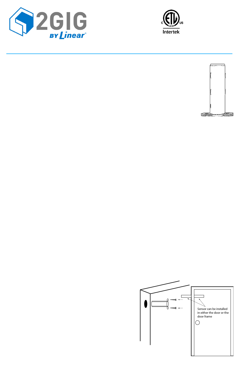
Installing and Mounting
If possible, locate sensors within 100 ft. (30 m) of the Control Panel. While a
transmitter may have a range of 450 ft. (137 m) or more out in the open, the
environment at the installation site can have a significant effect on transmitter
range.
Mounting Tools
•
Drill
•
11/16” Drill Bit
•
Marker or Pencil
FCC ID: WDQ‐DW20345
Industry Canada ID: 7794A‐DW20345
RECESSED DOOR CONTACT