Rc g a – 2GIG CT100 User Manual
Page 14
PG
14
14
W Y R G
W
IR
ES
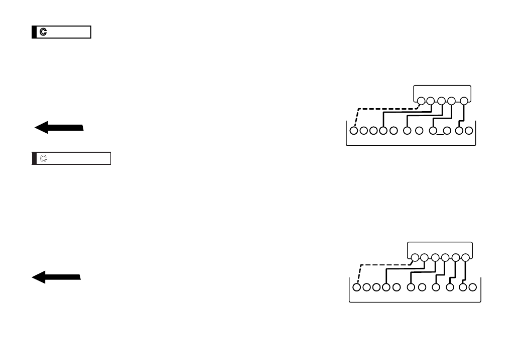
4 Wire Heat/Cool
STEP 1 - Connect the W wire to the W terminal. This connects the heat.
STEP 2 - Connect the Y wire to the Y terminal. This connects the cooling compressor.
STEP 3 - Connect the RH or R wire to the RH terminal. This connects the power.
STEP 4 - Connect the G wire to the G terminal on the thermostat.
This connects the fan.
STEP 5 - Optional - Connect the C wire to the C terminal.
Your HVAC system is now connected to the CT100.
Please Go To Page 6
W Y RH RC G
W
IR
ES
5 Wire HEAT/Cool
STEP 1 - Connect the W wire to the W terminal. This connects the heat.
STEP 2 - Connect the Y wire to the Y terminal. This connects to the cooling compressor.
STEP 3 - Remove the jumper between RC and RH terminals [small silver wire].
STEP 4 - Connect the RH wire to the RH terminal and the RC wire to the RC terminal.
This connects the power.
STEP 5 - Connect the G wire to the G terminal. This connects the fan.
STEP 6 - Optional - Connect the C wire to the C terminal.
Your HVAC system is now connected to the CT100.
Please Go To Page 6
HVAC SYSTEM
THERMOSTAT TERMINALS
C B O W W
2
Y Y
2
R
H
RC G A
POWER
W Y R
G
C
HVAC SYSTEM
THERMOSTAT TERMINALS
C B O W W
2
Y Y
2
R
H
RC G A
POWER
W Y R
H
G
C
R
C
*R
C and
R
H
disconnected