AEM Infinity Supported Applications - Toyota 1993-1997 Supra Turbo User Manual
Page 14
14
© 2014 AEM Performance Electronics
Infinity
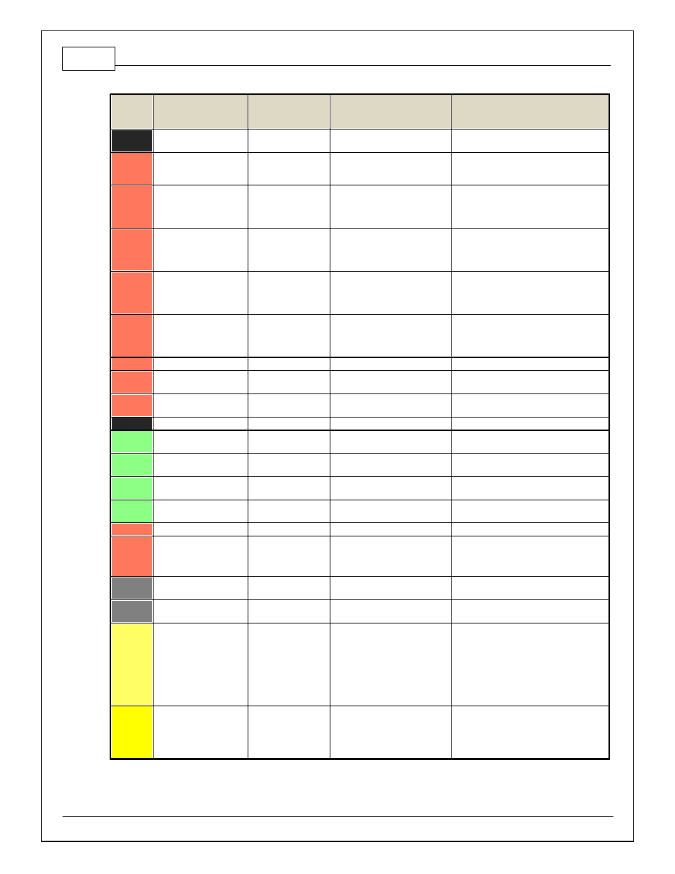
Pin
Hardware Reference
7100-XXXX-62
7101-XXXX-63
Function
Hardware Specification
Notes
C1-67
Analog_In_Temp_2
Intake Air
Temperature
12 bit A/D, 2.49K pullup to 5V
See "Air Temperature" Setup Wizard f or
selection.
C1-68
Harness_Analog_In_Temp
_3
Oil Temperature
Sensor
12 bit A/D, 2.49K pullup to 5V
See 1D table OilTempCal table f or
calibration data and OilTemp [C] f or channel
data.
C1-69
Stepper_2A
Stepper 2A
Automotiv e, Programmable
Stepper Driv er, up to 28V and
±1.4A
Be sure that each internal coil of the
stepper motor are properly paired with the
1A/1B and 2A/2B ECU outputs. Supports Bi-
Polar stepper motors only .
C1-70
Stepper_1A
Stepper 1A
Automotiv e, Programmable
Stepper Driv er, up to 28V and
±1.4A
Be sure that each internal coil of the
stepper motor are properly paired with the
1A/1B and 2A/2B ECU outputs. Supports Bi-
Polar stepper motors only .
C1-71
Stepper_2B
Stepper 2B
Automotiv e, Programmable
Stepper Driv er, up to 28V and
±1.4A
Be sure that each internal coil of the
stepper motor are properly paired with the
1A/1B and 2A/2B ECU outputs. Supports Bi-
Polar stepper motors only .
C1-72
Stepper_1B
Stepper 1B
Automotiv e, Programmable
Stepper Driv er, up to 28V and
±1.4A
Be sure that each internal coil of the
stepper motor are properly paired with the
1A/1B and 2A/2B ECU outputs. Supports Bi-
Polar stepper motors only .
C1-73
Power Ground
Ground
Power Ground
Connect directly to battery ground.
C2-1
DBW2 Motor +
DBW Motor Control
Open
5.0A max Throttle Control Hbridge
Driv e
+12V to open
C2-2
DBW2 Motor -
DBW Motor Control
Close
5.0A max Throttle Control Hbridge
Driv e
+12V to close
C2-3
Power Ground
Ground
Power Ground
Connect directly to battery ground.
C2-4
Injector 7
Injector 7
Saturated or peak and hold, 3A
max continuous
Injector 7
C2-5
Injector 8
Injector 8
Saturated or peak and hold, 3A
max continuous
Injector 8
C2-6
Injector 9
Injector 9
Saturated or peak and hold, 3A
max continuous
Injector 9
C2-7
Injector 10
Injector 10
Saturated or peak and hold, 3A
max continuous
Injector 10
C2-8
Power Ground
Ground
Power Ground
Connect directly to battery ground.
C2-9
+12V
+12V In
12 v olt power f rom relay
12 v olt power f rom relay . Relay must be
controlled by +12V Relay Control signal, pin
C1-29 abov e.
C2-10
Injector 11
Injector 11
Saturated or peak and hold, 3A
max continuous
Not used
C2-11
Injector 12
Injector 12
Saturated or peak and hold, 3A
max continuous
Not used
C2-12
Analog_In_17
A/C Analog Request
12 bit A/D, 100K pullup to 5V
0–5V analog signal. Use +5V Out pins as
power supply and Sensor Ground pins as
the low ref erence. Do not connect signals
ref erenced to +12V as this can permanently
damage the ECU. See Setup Wizard Input
Functions page f or input selection. See
AC_Request_In 1-axis table f or activ ation
logic.
C2-13
Analog_In_18
DBW_APP1 [%]
12 bit A/D, 100K pullup to 5V
0–5V analog signal. Use +5V Out pins as
power supply and Sensor Ground pins as
the low ref erence. Do not connect signals
ref erenced to +12V as this can permanently
damage the ECU.