Infinity supported application 11 – AEM Infinity Supported Applications - Toyota 1993-1997 Supra Turbo User Manual
Page 11
Infinity Supported Application
11
© 2014 AEM Performance Electronics
Infinity
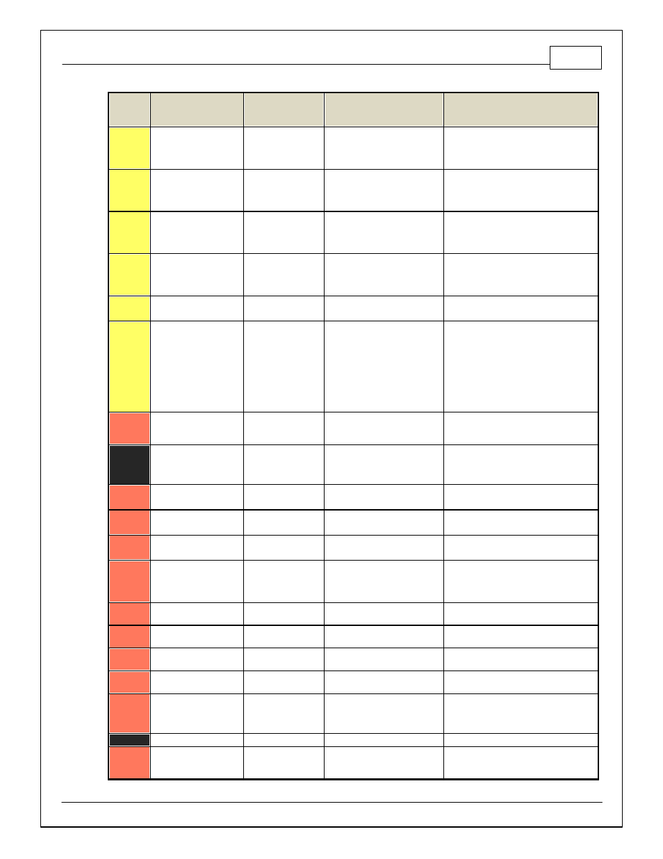
Pin
Hardware Reference
7100-XXXX-62
7101-XXXX-63
Function
Hardware Specification
Notes
C1-13
Coil 2
Coil 2
25 mA max source current
0–5V Falling edge f ire. DO NOT connect
directly to coil primary . Must use an ignitor
OR CDI that accepts a FALLING edge f ire
signal.
C1-14
Coil 1
Coil 1
25 mA max source current
0–5V Falling edge f ire. DO NOT connect
directly to coil primary . Must use an ignitor
OR CDI that accepts a FALLING edge f ire
signal.
C1-15
Coil 6
Coil 6
25 mA max source current
0–5V Falling edge f ire. DO NOT connect
directly to coil primary . Must use an ignitor
OR CDI that accepts a FALLING edge f ire
signal.
C1-16
Coil 5
Coil 5
25 mA max source current
0–5V Falling edge f ire. DO NOT connect
directly to coil primary . Must use an ignitor
OR CDI that accepts a FALLING edge f ire
signal.
C1-17
LowsideSwitch_2
Coolant Fan 1 Control
Lowside switch, 4A max, NO
internal f ly back diode.
See "LowSide Assignment Tables" f or output
assignment.
C1-18
LowsideSwitch_3
MIL Output
Lowside switch, 4A max with
internal f ly back diode. Inductiv e
load should NOT hav e f ull time
power.
See Wizard page "LowSide Assignment
Tables" f or output assignment.
MIL Activ ates when any of the f ollowing
f lags are true: ErrorAirTemp, ErrorBaro,
ErrorCoolantTemp, ErrorEBP,
ErrorFuelPressure, UEGO_0_Diag_error,
UEGO_1_Diag_error, ErrorMAFAnalog,
ErrorMAFDigital, ErrorMAP,
ErrorOilPressure, ErrorThrottle.
C1-19
AGND_1
Sensor Ground
Dedicated analog ground
Analog 0–5V sensor ground
C1-20
AGND_1
Sensor Ground
Dedicated analog ground
Analog 0–5V sensor ground
C1-21
Crankshaf t Position
Sensor Hall
Crankshaf t Position
Sensor Hall
10K pullup to 12V. Will work with
ground or f loating switches.
See Setup Wizard page Cam/Crank f or
options.
C1-22
Camshaf t Position Sensor
1 Hall
Camshaf t Position
Sensor 1 Hall
10K pullup to 12V. Will work with
ground or f loating switches.
See Setup Wizard page Cam/Crank f or
options.
C1-23
Digital_In_2
Camshaf t Position
Sensor 2 Hall
10K pullup to 12V. Will work with
ground or f loating switches.
See Setup Wizard page Cam/Crank f or
options.
C1-24
Digital_In_3
Turbo Speed Hz
10K pullup to 12V. Will work with
ground or f loating switches.
See Setup Wizard page Input Function
Assignment f or calibration constant.
TurboSpeed [RPM] = Turbo [Hz] * Turbo
Speed Calibration.
C1-25
Digital_In_4
Vehicle Speed Sensor
10K pullup to 12V. Will work with
ground or f loating switches.
See Setup Wizard page Input Function
Assignment f or calibration constant.
C1-26
Digital_In_5
Flex Fuel
10K pullup to 12V. Will work with
ground or f loating switches.
See channel FlexDigitalIn [Hz] f or raw
f requency input data.
C1-27
Knock Sensor 1
Knock Sensor 1
Dedicated knock signal
processor
See Setup Wizard page Knock Setup f or
options.
C1-28
Knock Sensor 2
Knock Sensor 2
Dedicated knock signal
processor
See Setup Wizard page Knock Setup f or
options.
C1-29
+12V_Relay _Control
+12V Relay Control
0.7A max ground sink f or external
relay control
Will activ ate at key on and at key of f
according to the conf iguration settings.
C1-30
Power Ground
Ground
Power Ground
Connect directly to battery ground.
C1-31
CANL_Aout
AEMNet CANL
Dedicated High Speed CAN
Transceiv er
Recommend twisted pair (one twist per 2")
with terminating resistor. Contact AEM f or
additional inf ormation.