AEM 30-6311 Series 2 Plug & Play EMS User Manual
Page 8
Page 8 of 12
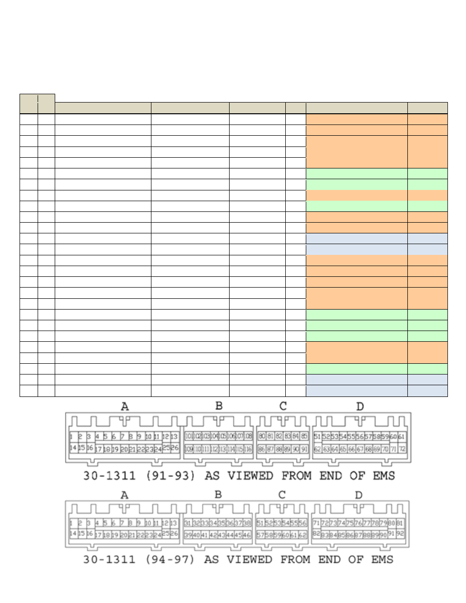
Connection Diagram for EMS P/N 30-6311
1991-97 Mitsubishi 3000GT VR4, Dodge Stealth TT
PnP
Means the Plug and Play system comes with this configured for proper operation of this device. Is still available for reassignment by the end user.
Avail
Means the function is not currently allocated and is available for use
Dedicated Means the location is fixed and cant be changed
91-93 94-97
Pin Pin
91-93 3000 GT
94-97 3000 GT
AEM EMS 30-6311
I/O
91-93 Notes
94-97 Notes
1
1
Injector 1
<---
Injector 1 P&H
Output Injector 1 (Peak/Hold 4A/1A driver)
<--
2
2
Injector 3
<---
Injector 3 P&H
Output Injector 3 (Peak/Hold 4A/1A driver)
<--
3
3
Injector 5
<---
Injector 5 P&H
Output Injector 5 (Peak/Hold 4A/1A driver)
<--
4
4
Idle Speed Control Servo (pin 1)
<---
Idle 1
Output
PnP for Stepper Idle Motor
<--
5
5
Idle Speed Control Servo (pin 4)
<---
Idle 3
Output
PnP for Stepper Idle Motor
<--
6
6
EGR Solenoid Valve
<---
Injector 8
Output Avail, Switched Ground, 1.5A max
<--
7
7
Fuel Pressure Solenoid
<---
Switch 4
Input Avail, switch must connect to ground
<--
8
8
MFI Relay (fuel pump)
<---
Low Side 11
Output
PnP for Fuel Pump relay
<--
9
9
EVAP Purge Solenoid Valve
<---
Low Side 4
Output Avail, Switched Ground, 1.5A max
<--
10
10
Ignition Power Transistor (1&4)
<---
Coil 1
Output PnP for Coil 1, rising edge trigger
<--
11
11
Ignition Power Transistor (3&6)
<---
Coil 3
Output PnP for Coil 3, rising edge trigger
<--
12
12
MFI Relay Power IN (main)
<---
+12V Switched
Input
Dedicated, +12V when relay is on
<--
13
13
Ground
<---
Ground
Input
Dedicated
<--
14
14
Injector 2
<---
Injector 2 P&H
Output Injector 2 (Peak/Hold 4A/1A driver)
<--
15
15
Injector 4
<---
Injector 4 P&H
Output Injector 4 (Peak/Hold 4A/1A driver)
<--
16
16
Injector 6
<---
Injector 6 P&H
Output Injector 6 (Peak/Hold 4A/1A driver)
<--
17
17
Idle Speed Control Servo (pin 3)
<---
Idle 2
Output
PnP for Stepper Idle Motor
<--
18
18
Idle Speed Control Servo (pin 6)
<---
Idle 4
Output
PnP for Stepper Idle Motor
<--
19
19
Maf reset switch
<---
Low Side 8
Output Avail, Switched Ground, 1.5A max
<--
20
20
A/C clutch slip input
Rad Fan High
Low Side 9
Output Avail, Switched Ground, 1.5A max
Rad Fan 2
21
21
Fuel Pump Relay (low speed)
Rad Fan Low
Low Side 2
Output Avail, Switched Ground, 1.5A max
Rad Fan 1
22
22
Magnetic Clutch Relay
<---
Low Side 6
Output
PnP for A/C Compressor
<--
23
23
Ignition Power Transistor (2&5)
<---
Coil 2
Output PnP for Coil 2, rising edge trigger
<--
24
24
Electrical Load (input)
<---
Switch 3
Input Avail, switch must connect to ground
<--
25
25
MFI Relay Power IN (main)
<---
+12V Switched
Input
Dedicated, +12V when relay is on
<--
26
26
Ground (in)
<---
Ground
Input
Dedicated
<--