AEM 30-6101 Series 2 Plug & Play EMS User Manual
Page 9
Page 9 of 13
This product is legal in California for racing vehicles only and should never be used on public highways.
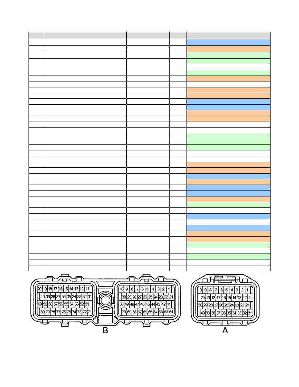
Connection Diagram for EMS P/N 30-6101
Pin#
93-97 Supra/Lexus 2JZ-GE
AEM P/N 30-6101
I/O
Availability & Notes
1A
Ignition Switch (+12V when key on)
Main Relay circuit
Input
Dedicated, activates Switch 1 input
2A
Vehicle Speed Signal
– from Odo/Trip meter
T3 (Vehicle Speed)
Input
PnP for Vehicle Speed signal
3A
Kickdown switch
Switch 3
Input
Available, switch must connect to GND
4A
Brake switch input (12V)
Switch 6
Input
Available, switch must connect to GND
5A
---
---
---
Not Used
6A
W- Malfunction Indicator Lamp
LS10
Output
Available, switched GND output (1.5A max)
7A
---
ATPR (GEAR)
Input
Reserved for future use
8A
SDL to datalink connector (96-97 only)
---
---
Not Used
9A
2nd gear indicator input (A/T only)
ATP2 (GEAR)
Input
Reserved for future use
10A
1st gear indicator input (A/T only)
ATP1 (GEAR)
Input
Reserved for future use
11A
---
CAN1L
Output
Dedicated
12A
OD1 to cruise control ECU (AT only)
CAN1H
Output
Dedicated
13A
---
Reserved
---
Reserved for future use
14A
---
Reserved
---
Reserved for future use
15A
ELS for Idle up Diode
---
---
Not Used
16A
Tacho signal (from ignitor)
---
---
Not Used
17A
TT sig to DATALINK connector (A/T only)
Injector 12
Output
Available, P&H Injector driver 4A/1A
18A
A/T pattern select sw (A/T only)
Switch 5
Input
Available, switch must connect to GND
19A
TE2 sig to DATALINK connector
Injector 11
Output
Available, P&H Injector driver 4A/1A
20A
TE1 sig to DATALINK connector
---
---
Not Used
21A
DI from Fuel Pump ECU
---
---
Not Used
22A
Fuel pump control (FPC) signal
Coil 8 / LS8
Output
PnP 0- 5V FPC signal, not for use with relays
23A
ACMG to A/C Magnetic clutch
LS6
Output
PNP for A/C compressor relay
24A
Main Relay Control
Main Relay (HS2)
Output
Dedicated, activates Main Relay with 12V
25A
Manual indicator light (A/T only)
ATIND (Coil7)
Output
PNP manual mode indicator (auto only)
26A
---
EFI-TRC
Input
Dedicated
27A
---
EFI+TRC
Input
Dedicated
28A
Over Drive Switch input (A/T only)
Switch 4
Input
PNP for Overdrive input (auto only)
29A
---
Baro (ADCR12)
Input
Available, Spare 0-5V Sensor Input
30A
Sub O2 signal (CA only)
---
---
Not Used
31A
+12V Power from main relay
+12V Switched
Both
Dedicated
32A
+12V Power from main relay
---
---
Not Used
33A
+12V permanent battery backup power
Permanent +12V
Input
Dedicated, used to store internal datalog
34A
A/C signal from A/C amplifier
ADCR11 (Switch 7)
Input
PNP for Air Conditioning request switch
35A
---
HALLPWR
Output
+12V Output
36A
Sub O2 sensor heater control (CA only)
Injector 8
Output
Spare P&H Injector 4A/1A
37A
---
---
---
Not Used
38A
---
LS7
---
Available, switched GND output (1.5A max)
39A
---
---
---
Not Used
40A
---
---
---
Not Used
WARNING: pin labeling scheme follows Toyota service manual convention; diagram shows wire side of
connector. Pin labels molded into plastic connector may not be accurate, check diagram carefully.