AEM 30-6101 Series 2 Plug & Play EMS User Manual
Page 11
Page 11 of 13
This product is legal in California for racing vehicles only and should never be used on public highways.
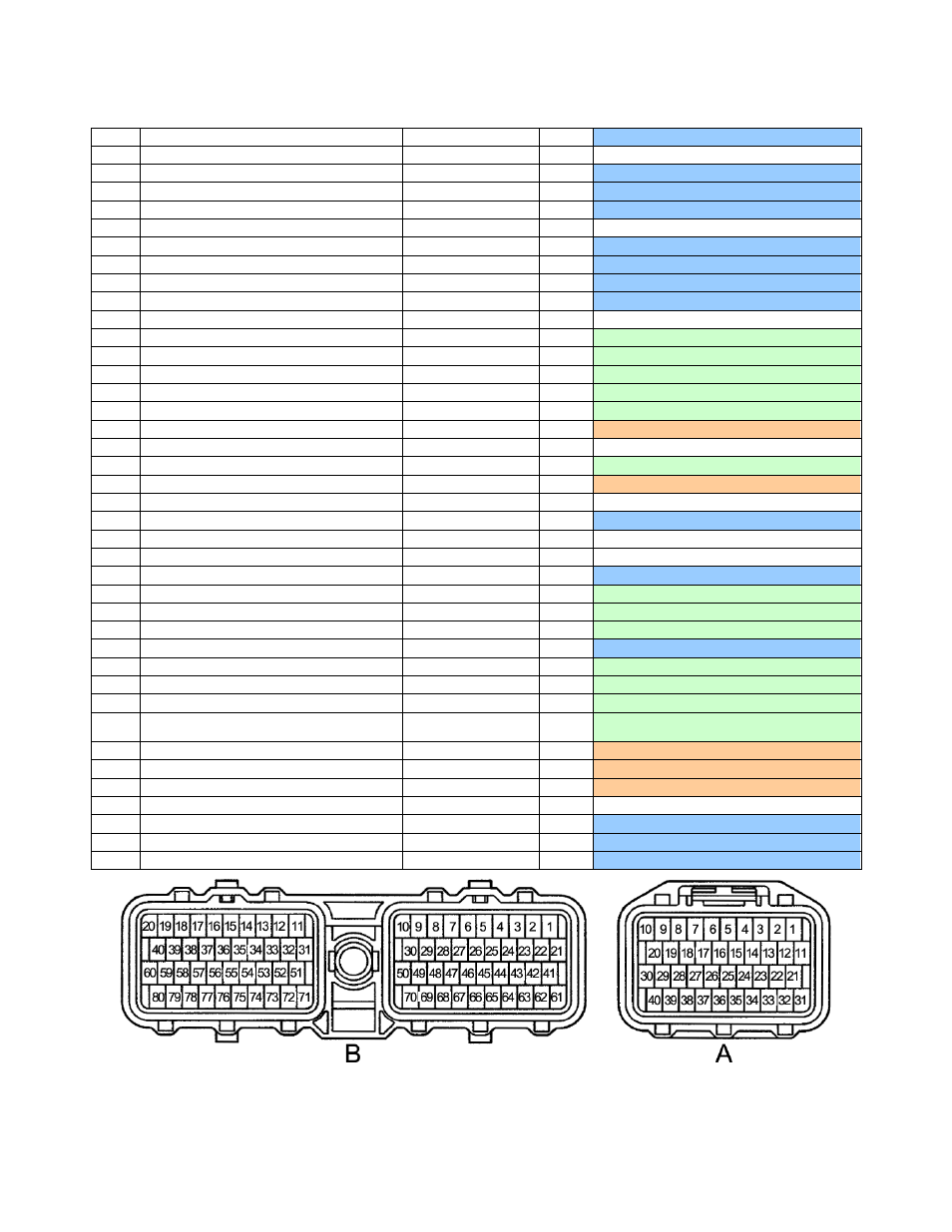
Connection Diagram for EMS P/N 30-6101
41B
5V Reference
+5V Sensor
Output
Dedicated
42B
---
---
---
Not Used
43B
TPS signal input (VTA1)
TPS
Input
Dedicated, 2
.2kΩ pull-up resistor to 5V
44B
Coolant Sensor Input
Coolant
Input
Dedicated
, 2.2kΩ pull-up resistor to 5V
45B
Air Temp Sensor
Air Temp
Input
Dedicated
46B
EGR gas Temp Sensor
---
---
Not Used
47B
OX2 (rear O2 sensor)
O2 #1
Input
Dedicated, 0-5V signal
48B
OX1 (front O2 sensor)
O2 #2
Input
Dedicated, 0-5V signal
49B
Rear Knock Sensor
Knock 2
Input
Dedicated, software knock filter
50B
Front Knock Sensor
Knock 1
Input
Dedicated, software knock filter
51B
---
---
---
Not Used
52B
---
Coil 6
Output
Avail. Coil6 output, 0-5V falling edge trigger
53B
---
Coil 5
Output
Avail. Coil5 output, 0-5V falling edge trigger
54B
---
Coil 4
Output
Avail. Coil4 output, 0-5V falling edge trigger
55B
---
Coil 3
Output
Avail. Coil3 output, 0-5V falling edge trigger
56B
---
Coil 2
Output
Avail. Coil2 output, 0-5V falling edge trigger
57B
Igniter Control (IGT)
Coil 1
Output
PnP Coil1 output, 0-5V falling edge trigger
58B
Igniter return (IGF) to ECU
---
---
Not Used
59B
---
LS11
Output
Available Switched Ground 1.5amp max
60B
---
PW2
Output
Available boost control solenoid output
61B
---
---
---
Not Used
62B
---
MAP
Input
Dedicated
63B
---
---
---
Not Used
64B
Idle1 Sw from TPS
---
---
Not Used
65B
Sensor Ground
Sensor Ground
Output
Dedicated, Sensors only
66B
VG signal for Airflow meter
MAF
Input
Available 0 to 5v input, 100k pull-up to 5V
67B
---
EGT 4
Input
Jumper: 0-5V, thermistor or EGT pull up
68B
---
LS9
Output
Available Switched Ground 1.5amp max
69B
E1- Ground
Power Ground
Both
Dedicated
70B
---
Injector 7
Output
Available P&H Injector driver 4A/1A
71B
Ox 1 Heater Ground (96-97)
LS12
Output
Available Switched Ground 1.5amp max
72B
HT2
– rear O2 heater control (CA only)
LS2
Output
Available Switched Ground 1.5amp max
73B
HT1
– front O2 heater control (CA only) /
Fuel Pressure up solenoid (1997)
LS1
Output
Available Switched Ground 1.5amp max
74B
EVAP Solenoid
Injector 9
Output
Available P&H Injector driver 4A/1A
75B
EGR Solenoid
Injector 10
Output
Available P&H Injector driver 4A/1A
76B
Park / Neutral position switch (AT only)
ATPNP (Gear)
Input
Reserved for future use
77B
Cranking signal input (12V)
---
---
Not Used
78B
Chassis Ground - EO3 (96-97)
Power Ground
Both
Dedicated
79B
Chassis Ground
– EO2
Power Ground
Both
Dedicated
80B
Chassis Ground
– EO1
Power Ground
Both
Dedicated
WARNING: pin labeling scheme follows Toyota service manual convention; diagram shows wire side of
connector. Pin labels molded into plastic connector may not be accurate, check diagram carefully.